
Adjustable flow energy dissipator installed inside the vessel for nuclear power plant

A nuclear power plant, adjustable technology, applied in the valve device, valve detail, valve operation/release device, etc., can solve the problem of increasing the length and size of the circuit, and achieve the effect of reducing vibration and noise, ensuring stability, and reducing fluctuations

Active Publication Date: 2019-07-02
CHINA NUCLEAR POWER DESIGN COMPANY +2
View PDF7 Cites 0 Cited by
  • Summary
  • Abstract
  • Description
  • Claims
  • Application Information

AI Technical Summary

Problems solved by technology

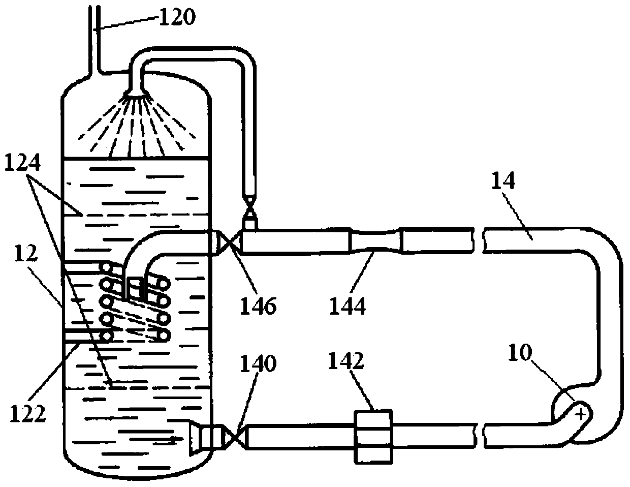
It can be seen that the existence of the flow regulating valve 146 and the installation location requirements lead to an increase in the length of the loop

Method used


Image

  • Adjustable flow energy dissipator installed inside the vessel for nuclear power plant
  • Adjustable flow energy dissipator installed inside the vessel for nuclear power plant
  • Adjustable flow energy dissipator installed inside the vessel for nuclear power plant

Examples


Embodiment Construction

[0022] In order to make the purpose, technical solution and beneficial technical effects of the present invention clearer, the present invention will be further described in detail below in conjunction with the accompanying drawings and specific embodiments. It should be understood that the specific implementations described in this specification are only for explaining the present invention, not for limiting the present invention.

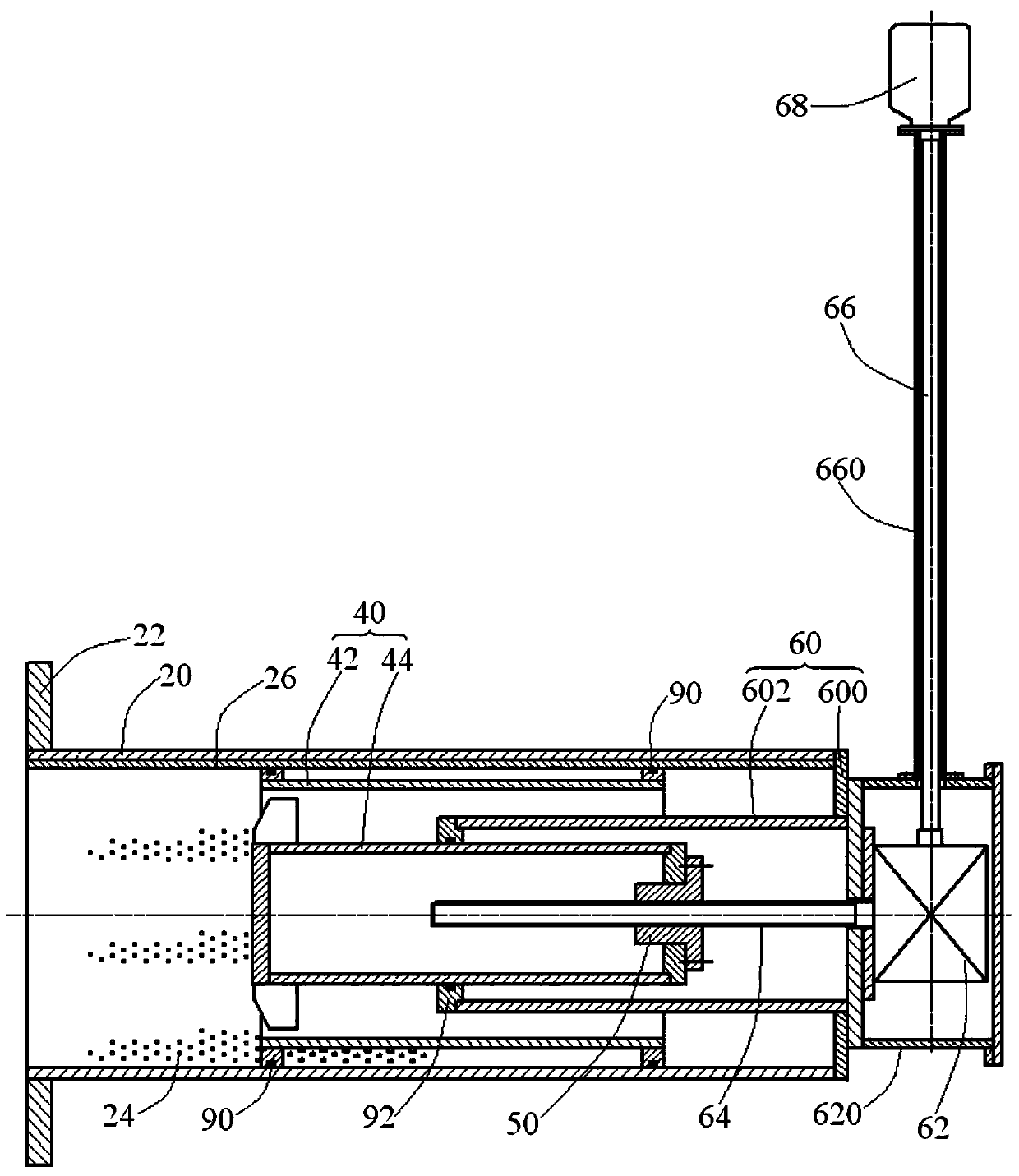
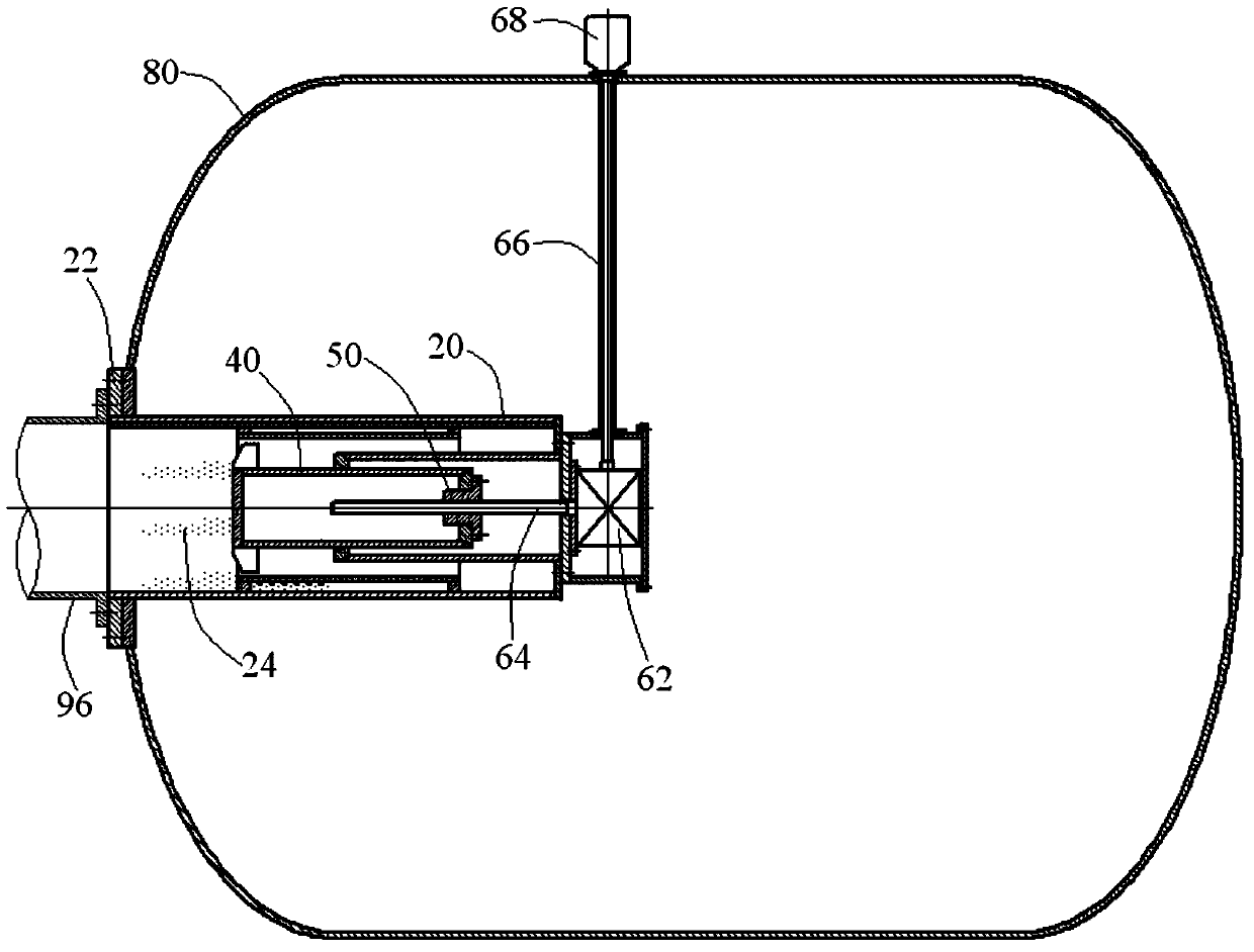
[0023] see figure 2 , the adjustable flow energy dissipator installed inside the container for nuclear power plants of the present invention includes a cylinder 20, a piston 40 and a piston driving device located in the cylinder 20, and the piston 40 can move along the cylinder 20 under the drive of the piston driving device. axial movement.

[0024] A flange 22 for fixing is provided on the peripheral wall of the front end of the cylinder 20, and a plurality of through holes 24 distributed according to a certain rule are opened on the periphera...


PUM


Abstract

The invention discloses a flow adjustment energy dissipation device installed inside a container and used for a nuclear power plant. The flow adjustment energy dissipation device comprises a cylinder installed inside the container, a piston arranged in the cylinder, and a piston driving device used for driving the piston. A plurality of through holes are formed in the peripheral wall of the cylinder. The piston is driven by the piston driving device to move along the cylinder in the axial direction, so that the number of the through holes through which liquid passes is changed, the flow of the liquid is adjusted, and the flowing direction of the liquid is changed from the axial direction to the radial direction. Compared with the prior art, according to the flow adjustment energy dissipation device installed inside the container and used for the nuclear power plant, the multiple through holes are formed in the peripheral wall of the cylinder, so that the energy of the liquid entering the container is dissipated; in addition, by changing the number of the through holes through which the liquid passes, the liquid flow is adjusted through the axial movement of the piston; in this way, fluctuation, vortexes and turbulent flow generated by the liquid in the container can be effectively reduced, the stability of the liquid at an irrigating gate of a pump is guaranteed, and the vibration and noise generated by a circuit system are greatly reduced.

Description

technical field [0001] The invention relates to a liquid circulation closed loop system of a nuclear power plant, and more specifically, the invention relates to an adjustable flow energy dissipator installed inside a container. Background technique [0002] In a liquid circulation closed loop system consisting of pressure vessels, pumps, valves, pipelines, etc., the liquid in the vessel is powered by the pump (extraction, pressurization) to circulate in the loop. The above-mentioned loop system generally sets a flow regulating valve on the downstream pipeline of the pump. By changing the opening of the regulating valve, the hydraulic performance (flow-lift, flow-efficiency, etc.) of the pump can be tested. However, when the liquid in the closed circuit enters the container after being pressurized by the pump, the energy is relatively high, and the liquid flow with the same inner diameter as the pipe is sprayed in a single direction in the axial direction in the container, a...

Claims


Application Information

Patent Timeline
Patent Type & Authority Patents(China)
IPC IPC(8): F16K3/24F16K3/314F16K3/316F16K27/04F16K47/02F16K47/08F16K31/04F16K31/50
CPCF16K3/24F16K3/314F16K3/316F16K27/041F16K31/047F16K31/508F16K47/08
Inventor 张铁坚张巍王学灵丛国辉陈兴江
Owner CHINA NUCLEAR POWER DESIGN COMPANY
Learn More