
A Biomass Combustion Furnace with Steady Feed Wind and Less Sparks

A biomass burning furnace, stable technology, applied in household stoves/stoves, solid heating fuel, lighting and heating equipment, etc., can solve the problems of uneven heating of cooking pots, large differences in flue pressure, etc., and achieve dust emission and pollutant reduction, good environmental performance, and stable work

Active Publication Date: 2018-11-13
FUZHOU SUNSHI XIONGDI IND
View PDF11 Cites 0 Cited by
  • Summary
  • Abstract
  • Description
  • Claims
  • Application Information

AI Technical Summary

Problems solved by technology

Due to the position and quantity of the flue gas outlet, the flue gas pressure in each area of ​​the furnace varies greatly, that is, the resistance to the flow of flue gas in each area of ​​the furnace varies greatly, and the flame tends to the flue gas outlet, causing the cooking pot to be heated. uneven

Method used


Image

  • A Biomass Combustion Furnace with Steady Feed Wind and Less Sparks
  • A Biomass Combustion Furnace with Steady Feed Wind and Less Sparks
  • A Biomass Combustion Furnace with Steady Feed Wind and Less Sparks

Examples


Embodiment 1

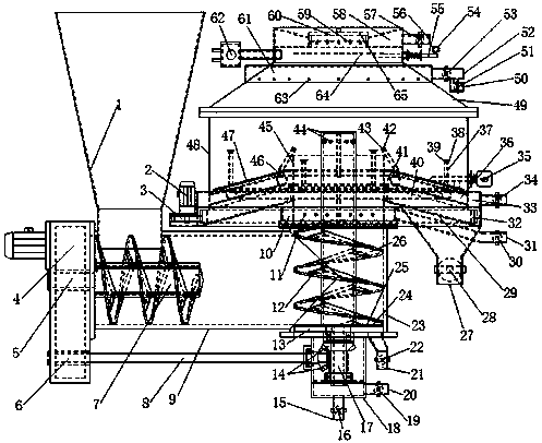
[0039] The upper end of the vertical feeding pipe 23 is connected with the lower end of the furnace feeding pipe 45 , and the lower end of the vertical feeding pipe 23 is connected with the vertical spiral support 18 . The side of vertical feed pipe 23 has feed inlet and is connected with horizontal feed pipe 9, and the other port of horizontal feed pipe 9 is connected with gearbox 4, and the end is connected with funnel 1 upwards.

[0040] The horizontal screw 7 is connected to the A output end 5, and the spiral body of the horizontal screw 7 is located below the funnel mouth of the funnel 1. Therefore, the horizontal screw 7 is rotationally connected with the horizontal feed pipe 9 through the A output end 5, and driven by the A output end 5 Lower horizontal feeding.

[0041]The B output end 6 of the gearbox is connected with one end of the transmission shaft 8, and the vertical spiral support 18 is provided with a bevel gear set 14, and the other end of the transmission sha...

Embodiment 2

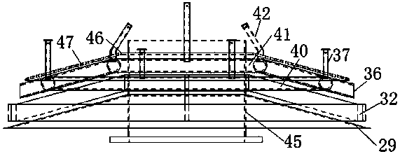
[0064] The upper furnace hearth 249 of the open shape is a round frustum annular structure, and the opening of the upper furnace hearth 249 of the open shape is a pot shape, and the upper port of the furnace hearth 48 is connected with the bottom port of the upper furnace hearth 249 of the open shape, and the bottom of the upper furnace hearth 249 of the open shape is provided with an ignition air outlet. Band 61; the upper and lower inner circles of the ignition wind belt 61 are connected with the bottom outer wall of the open-shaped upper furnace 249, and the bottom of the open-shaped upper furnace 249 is evenly opened on the same circumference with respect to the position of the ignition wind belt 61. Hole 63.

[0065] One end of the ignition gas valve 51 is connected with the ignition air inlet pipe 52, and the other end is the ignition gas inlet 50. One end of ignition air belt valve 53 is connected with ignition air inlet pipe 52, and the other end is connected with igni...


PUM


Abstract

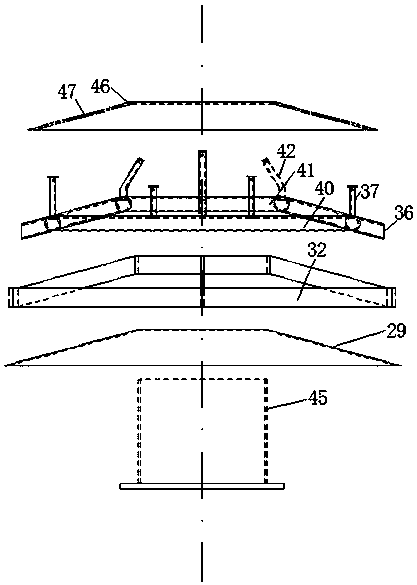
The invention discloses a biomass combustion furnace with stable material air and few sparks. The biomass combustion furnace comprises a horizontal feeding device, a vertical feeding device, a hearth feeding pipe, an ash discharge device, a hearth, an upper hearth and various air ducts, wherein a hearth bottom of the hearth, an ash discharge gear of the ash discharge device, annular air duct air manifolds of the annular air ducts, and a vibrating screen are integrally in a circular table shaped annular shape, and the hearth bottom, the ash discharge gear and the annular air duct air manifolds and the vibrating screen are arranged from the bottom up sequentially. According to the biomass combustion furnace, the hearth bottom, the ash discharge gear, the annular air duct air manifolds and the vibrating screen that are integrally in a circular table shaped annular structure are assembled together, and a conical surface is formed at the hearth bottom, so that fuel can be dispersed towards the periphery easily and stably, and straight air pipes and bent air pipes can allow the air to be distributed in the same horizontal plane in the hearth more uniformly; and chip discharge grooves are uniformly formed in vane blade of a vertical screw, so that the sparks generated by combustion of chip-shaped objects are reduced, flue gas pressure of a flue gas emission channel is balanced, and the trends of the flames in the hearth are uniform.

Description

technical field [0001] The invention belongs to a solid fuel combustion furnace, and relates to a fully automatic feed biomass combustion furnace in which the fuel is combusted from top to bottom, in particular to a biomass combustion furnace with stable feed wind and less sparks. Background technique [0002] The combustion device that uses the top-down combustion method for fuel has been continuously developed. The existing feeding device is "closed biomass fuel feeding device", patent number: CN200820185125.6. The flap door device of the device, the flap door device is provided with a fuel inlet, the lower end of the screw device communicates with a metering silo, and the metering hopper is equipped with a fuel level detection device; another example is the applicant CN201110072163.7 of "A Fuel Feeding Device for Furnace with Full-automatic Feeding and Burner Furnace", which adopts the method of mobile replenishment and push-type feeding, and continuously promotes to real...

Claims


Application Information

Patent Timeline
Patent Type & Authority Patents(China)
IPC IPC(8): F24B1/20F24B13/04
CPCF24B1/20F24B13/04
Inventor 孙清刚陆振邦孙吉章
Owner FUZHOU SUNSHI XIONGDI IND
Learn More