Carbon thermal rail production line and carbon thermal rail production method

A production method, carbon hot rail technology, applied in the carbon hot rail production line and production field, can solve the problems of cold air existing in the lower layer, affecting people's rest, and uneven temperature distribution, so as to ensure safety, avoid fire escape, and improve production efficiency Effect

Inactive Publication Date: 2016-03-23
北京中科联众科技股份有限公司
View PDF7 Cites 1 Cited by
  • Summary
  • Abstract
  • Description
  • Claims
  • Application Information

AI Technical Summary

Problems solved by technology

Traditional geothermal heating mainly heats the room in two ways: conduction and convection. These two heating methods first heat the indoor air, and people in the room get heat from the air. However, the hot air in the room often rises to In the upper layer, the cold air exists in the lower layer, which leads to uneven distribution of indoor temperature, resulting in hot top and cool bottom
Radiators using convection must assist the fan to dissipate heat, but the noise of the fan during operation will affect people's rest

Method used


Image

  • Carbon thermal rail production line and carbon thermal rail production method
  • Carbon thermal rail production line and carbon thermal rail production method
  • Carbon thermal rail production line and carbon thermal rail production method

Examples


Embodiment 1

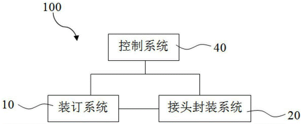
[0074] figure 2 It is a structural block diagram of a preferred embodiment of the carbon hot rail production line of the present invention, which shows the main components of a preferred embodiment of the carbon hot rail production line of the present invention.

[0075] The carbon hot rail production line 100 includes a binding system 10 , a joint packaging system 20 connected with the binding system 10 and a control system 40 connected with the binding system 10 and the joint packaging system 20 .

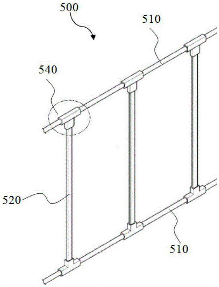
[0076] Among them, the binding system 10 is used to bind the power cord 510 and the carbon rod 520 in the carbon thermal rail 500; ; The control system 40 is used to control the binding system 10 and the joint packaging system 20 .

[0077] The carbon hot rail production line of the present invention can complete the binding and joint packaging of at least 500 carbon rods and power lines per hour, which can greatly improve the production efficiency of the carbon hot rail and re...

Embodiment 2

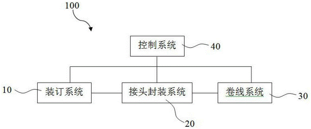
[0107] Compared with Embodiment 1, the carbon hot rail production line 100 of this embodiment also includes a winding system 30, such as figure 2 shown.

[0108] The winding system 30 is connected with the joint packaging system 20 and controlled by the control system 40, which is used for storing the finished carbon thermal rail. The winding system 30 can quickly complete the winding of the formed floor heating heat rail, improve the packaging efficiency of the carbon heat rail, and reduce the cost.

[0109] The carbon rods and power cords that have been packaged with joints are transported to the winding system 30 through the second feeding mechanism 230 .

[0110] Preferably, the winding system 30 is a winding machine.

[0111] preferred, such as Figure 12 As shown, the winding system 30 includes a winding reel 310 driven by a motor and a counting sensor 340 connected to the control system 40 . The winding system 30 is disposed on the third supporting platform 320 . ...


PUM


Abstract

The invention relates to a carbon thermal rail production line and a carbon thermal rail production method. The carbon thermal rail production line comprises a bookbinding system, a connector packaging system and a control system, wherein the bookbinding system is used for bookbinding power lines and carbon rods in a carbon thermal rail; the connector sealing system is connected with the bookbinding system, and is used for packaging the connection parts between the power lines and the carbon rods in the carbon thermal rail; and the control system is connected with the bookbinding system and the connector packaging system and controls the bookbinding system and the connector packaging system. The carbon thermal rail production line can complete the bookbinding and connector packaging of at least 500 carbon rods and power lines per hour, so that the production efficiency of the carbon thermal rail can be improved greatly, and the cost is reduced.

Description

technical field [0001] The invention relates to the technical field of floor heating production, in particular to a carbon heating rail production line and a production method. Background technique [0002] Carbon thermal rail is a new type of geothermal material, which is different from the traditional geothermal heating method. Traditional geothermal heating mainly heats the room in two ways: conduction and convection. These two heating methods first heat the indoor air, and people in the room get heat from the air. However, the hot air in the room often rises to In the upper layer, cold air exists in the lower layer, which leads to uneven distribution of indoor temperature, resulting in hot top and cool bottom. The radiators that adopt the convection method all have to assist the fan to dissipate heat, but the noise of the fan during operation will affect people's rest. The carbon rod heating rail is heated by infrared radiation and directly acts on the surface of the h...

Claims


Application Information

Patent Timeline
Patent Type & Authority Applications(China)
IPC IPC(8): F24D13/02F24D19/10
CPCF24D13/02F24D19/1096
Inventor 陈滨张雪芳底杏甫王浩
Owner 北京中科联众科技股份有限公司
Why Eureka
Try Eureka