Steel tube pressure test sealing apparatus and pressure test apparatus therewith for pressure test on multiple tubes

A sealing device and pressure testing technology, which is applied in the direction of applying stable tension/pressure to test the strength of materials, measuring devices, instruments, etc., can solve the problem of multiple screw rods setting costs and large waste of functions, many non-working hours, and structure Insufficient compactness and other problems, to achieve the effect of convenient adjustment, high efficiency and compact structure

Active Publication Date: 2016-03-23
QINGDAO ZHONGRUITAI MESNAC TECH CO LTD
View PDF7 Cites 2 Cited by
  • Summary
  • Abstract
  • Description
  • Claims
  • Application Information

AI Technical Summary

Problems solved by technology

In the multi-pipe pressure test, multiple test heads hold the steel pipe for pressure test respectively, and the test heads arranged side by side are suitable for steel pipes of different lengths, and if the screw nut is adopted, multiple screw rods need to be insta...

Method used


Image

  • Steel tube pressure test sealing apparatus and pressure test apparatus therewith for pressure test on multiple tubes
  • Steel tube pressure test sealing apparatus and pressure test apparatus therewith for pressure test on multiple tubes
  • Steel tube pressure test sealing apparatus and pressure test apparatus therewith for pressure test on multiple tubes

Examples


Embodiment approach 1

[0028] Embodiment 1 is an embodiment of the steel pipe pressure test sealing device involved in the present invention. figure 1 , figure 2 , image 3 , Figure 4 , Figure 5 illustrate.

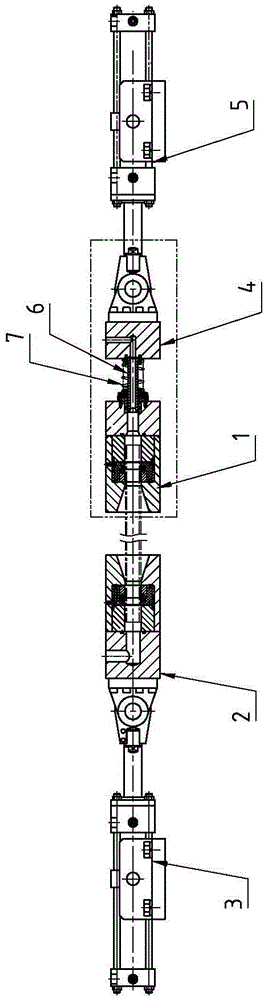
[0029] figure 1 In the middle, the first sealing head 1 is located on the right side, and the second sealing head 2 is located on the left side. The rear of the sealing head 1 is connected with the adjusting seat 4 by a piston 6 , the driving cylinder 5 is connected with the adjusting seat 4 , and the rear of the second sealing head 2 is connected with the driving cylinder 3 .

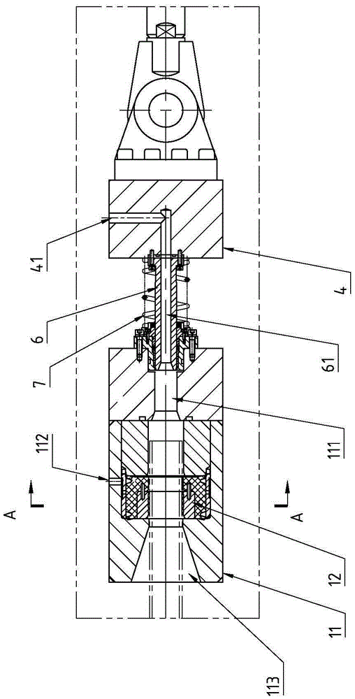
[0030] To make figure 1 The structure representation of the first sealing head and the adjustment seat in the image 3 for figure 1 Enlarged view of the double-dot dash line part; image 3 Among them, the first sealing head 1 includes a sealing seat 11 and a sealing ring 12, the sealing ring 12 is installed in the sealing seat 11, the sealing seat 11 is provided with a pipe end penetration hole 113, and the ...

Embodiment approach 2

[0038] Embodiment 2 is an embodiment of the pressure test device for multi-pipe pressure test using the steel pipe pressure test sealing device involved in the present invention. Image 6 , Figure 7 illustrate.

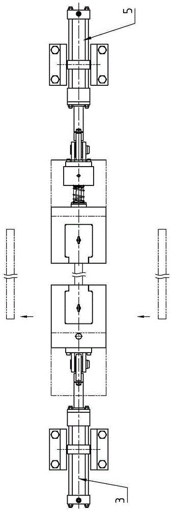
[0039] Image 6 The middle is a top view of a pressure test device that can test the pressure of 4 steel pipes. In the figure, 4 sets of pipe end pressure test sealing devices identical to Embodiment 1 are arranged in parallel, and 4 steel pipes of different lengths are tested simultaneously, and one steel pipe corresponds to a set of pipe end pressure test sealing devices; Image 6 As shown, the lower two steel pipes are longer, and the corresponding two sets of first sealing heads have a larger retreat range. The adjustment seat is relatively fixed, the first sealing head can move back and forth freely, the steel pipe is longer, and the range of retreat is larger, and the steel pipe is shorter, and the range of piston retreat is smaller, so as to realize the ada...


PUM


Abstract

The invention relates to the technical field of test equipment and particularly provides a steel tube pressure test sealing apparatus and a pressure test apparatus therewith for pressure test on multiple tubes. The sealing apparatus includes a first sealing head which includes a sealing base and a sealing ring. The sealing ring is installed in the sealing base. The sealing base is provided with a tube end inserting hole connected to an inner hole in the sealing ring. The sealing base is provided with a path, which is connected to the tube end inserting hole and the inner hole in the sealing ring and is introduced out from the sealing base. The sealing apparatus also includes an adjustment base being connected to the first sealing heat with a piston. The sealing apparatus conveniently adapts pressure test in steel tubes in different lengths, when being used in the pressure test on multiple tubes, at least two sets of the tube end pressure test sealing apparatus are arranged in parallel. The test sealing apparatus is more convenient to adjust the steel tubes in different lengths. The pressure test apparatus is more reasonable and compact in structure, achieves self-adaptive adjustment and is higher in efficiency.

Description

technical field [0001] The invention relates to the technical field of test equipment, in particular to a steel pipe pressure test sealing device and a pressure test device using the same for multi-pipe pressure test. Background technique [0002] In the hydrostatic test, the sealing device at the end of the steel pipe is a crucial part. During the pressure test process, the lengths of the steel pipes are different, and the existing steel pipe pressure test machine is adapted to the pressure test of steel pipes with different lengths through the form of screw nuts. In the multi-tube pressure test, multiple test heads hold the steel pipes for pressure test respectively, and the test heads arranged side by side are suitable for steel pipes of different lengths, and if the screw nut is used, it is necessary to set multiple screw rods, not only the structure It is not compact enough, and the cost and function of multiple screw rods are wasted. At the same time, more non-working...

Claims


Application Information

Patent Timeline
IPC IPC(8): G01N3/12G01N3/02
CPCG01N3/02G01N3/12
Inventor 王中华孙国胜段英良
Owner QINGDAO ZHONGRUITAI MESNAC TECH CO LTD
Why Eureka
Try Eureka