Combustion particle multi-parameter measurement device and method adopting blue-ray back lighting

A technology of backlighting and measuring devices, which is applied in measuring devices, particle suspension analysis, fluid velocity measurement, etc., can solve the problems of flame self-illumination and mutual interference between lighting backlights, avoid the influence of burning flames, and enrich measurement parameters , and deepen the effect of measurement parameters

Active Publication Date: 2016-03-23
UNIV OF SHANGHAI FOR SCI & TECH
View PDF11 Cites 14 Cited by
  • Summary
  • Abstract
  • Description
  • Claims
  • Application Information

AI Technical Summary

Problems solved by technology

[0005] The purpose of the present invention is to provide a multi-parameter measuring device and method for burning particles using blue light backlight to solve the technical problem of mutual interference between flame self-illumination and lighting backlight in the process of image acquisition, which has the advantages of simple implementation, convenient measurement and rich information specialty

Method used


Image

  • Combustion particle multi-parameter measurement device and method adopting blue-ray back lighting
  • Combustion particle multi-parameter measurement device and method adopting blue-ray back lighting
  • Combustion particle multi-parameter measurement device and method adopting blue-ray back lighting

Examples


Embodiment 1

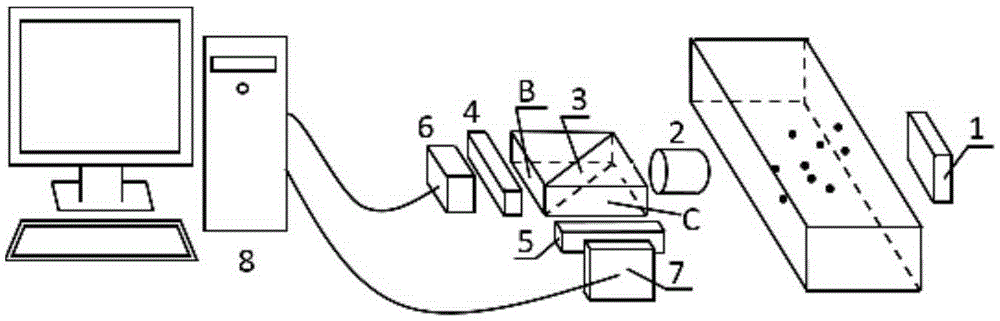
[0040] Such as figure 2 As shown, the device includes a blue light source 1, a camera composed of a lens 2, a beam splitter 3, a blue light bandpass filter 4, a blue light cut filter 5, a first image sensor 6, and a second image sensor 7. And computer 8; Illumination area 11 to be measured with blue light source 1 in the mode of backlight, dichroic prism 3 is installed on the back of first lens 2, and first lens 2 receives the light beam that blue light source 1 emits and measured particle scattering in area 11 to be measured The beam splitter 3 divides the light entering the first lens 2 into two beams with the same spectral composition and intensity. One beam is filtered by the blue light bandpass filter 4 and then received by the first image sensor 6, and the other beam is filtered by the first image sensor 6. After being filtered by the blue light cut filter 5, it is received by the second image sensor 7, and the first image sensor 6 and the second image sensor 7 convert ...

Embodiment 2

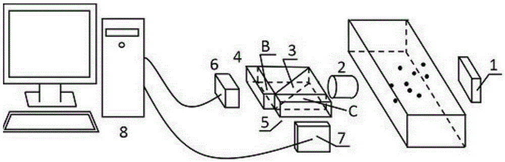
[0058] The blue light band-pass filter 4 and the blue light cut-off filter 5 among the embodiment 1 are plated on the surface of the first exit surface B and the second exit surface C of the beam splitter 3 in a film mode, as image 3 As shown, the beam splitter 3, the blue light bandpass filter 4 and the blue light cut filter 5 in the first embodiment constitute a whole, and the steps of the measurement method are the same as those in the first embodiment.

Embodiment 3

[0060] The blue light bandpass filter 4 and the blue light cut filter 5 in Embodiment 1 are screwed into the camera, that is, fixed in front of the first image sensor 6 and the second image sensor 7, as Figure 4 As shown, the measurement method steps are the same as in Example 1.


PUM


Abstract

The invention discloses a combustion particle multi-parameter measurement device and method adopting blue-ray back lighting. The device comprises a blue-ray light source, a camera and a computer, wherein the camera consists of a lens, a beam splitter, a blue-ray band-pass filter, a blue-ray cut-off filter, a first image sensor and a second image sensor. The blue-ray light source illuminates a region to be measured in a back lighting mode, the beam splitter is installed behind the lens, the lens receives light beams emitted by the blue-ray light source and light beams scattered by measured particles in the region to be measured, the beam splitter divides light entering the lens into two split light beams identical in spectral composition and intensity, one split light beam is filtered by the blue-ray band-pass filter and then is received by the first image sensor, the other split light beam is filtered by the blue-ray cut-off filter and then is received by the second image sensor, and the first image sensor and the second image sensor convert optical signals into television signals to be transmitted to the computer so as to perform image processing for characteristic information obtaining. The technical problem that flame self-emitted light and backlight for illumination are mutually interfered in the image acquisition process is solved.

Description

technical field [0001] The invention relates to the technical field of particle measurement using digital image means, in particular to a multi-parameter measuring device and method for burning particles using blue light backlighting. Background technique [0002] In recent years, with the development of camera and computer technology, image processing technology has been widely used in the field of particle and flow field measurement. For the combustion flame as a whole, this visualization technology using a CCD or CMOS camera to capture images can not only visually observe the structure, shape and motion characteristics of the flame, but also use a high-speed camera to analyze the flickering characteristics of the flame for flame fault detection. The principle of temperature measurement can also reconstruct the flame temperature field by analyzing the flame sequence images. The above measurements generally use the flame itself to emit light, and use a color camera or a bl...

Claims


Application Information

Patent Timeline
Patent Type & Authority Applications(China)
IPC IPC(8): G01N15/02G01N15/06G01N21/47G01P5/18
CPCG01N15/0227G01N15/06G01N21/4738G01N2015/0693G01N2021/4769G01P5/18
Inventor 周骛郑榕根蔡小舒杨斌
Owner UNIV OF SHANGHAI FOR SCI & TECH
Why Eureka
Try Eureka