Non-arc contactor
A contactor and contact group technology, applied in relays, electromagnetic relays, electromagnetic relay details and other directions, can solve the problems of inconvenient installation, potential safety hazards, complex structure, etc., and achieve the effect of improving life expectancy
- Summary
- Abstract
- Description
- Claims
- Application Information
AI Technical Summary
Problems solved by technology
Method used
Image

Examples
Embodiment Construction
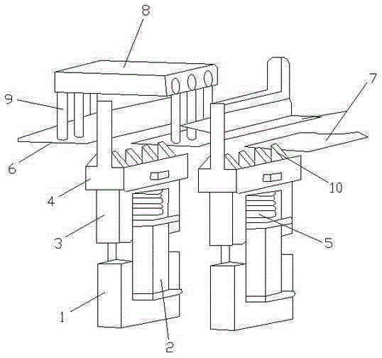
[0015] refer to figure 1 As shown, an arcless contactor includes a static iron core 1, a coil 2, a moving iron core 3 and a bracket 4, the static iron core 1 is provided with two, and the coil 2 is arranged in the static iron core 1, The moving iron core 3 is arranged on the static iron core 1, and the moving iron core 3 and the static iron core 1 are arranged correspondingly. The support 4 is arranged on the moving iron core 3, and the support 4 and the moving iron core 3 Fixed connection, when in use, when the current is overloaded, the electromagnetic force generated by the static iron core 1 at the bottom of the coil 2 is greater than the elastic force of the spring 5, so that the first contact group 6 and the second contact group 7 are disconnected, and the first contact group 6 and the second contact group 7 are disconnected. The triac module 8 connected in parallel with the contact group 6 prevents arcing when disconnected. The moving iron core 3 is provided with a spri...
PUM
 Abstract
Description
Claims
Application Information
 - R&D
- Intellectual Property
- Life Sciences
- Materials
- Tech Scout
- Unparalleled Data Quality
- Higher Quality Content
- 60% Fewer Hallucinations
Browse by: Latest US Patents, China's latest patents, Technical Efficacy Thesaurus, Application Domain, Technology Topic, Popular Technical Reports.
© 2025 PatSnap. All rights reserved.Legal|Privacy policy|Modern Slavery Act Transparency Statement|Sitemap|About US| Contact US: help@patsnap.com