

Stamping equipment applied to motor rotor punching sheet production
A technology of stamping equipment and motor rotor, applied in the field of stamping equipment, can solve the problems of increased labor intensity, unstable stamping performance, low stamping performance, etc., and achieve the effect of improving stability and precision
- Summary
- Abstract
- Description
- Claims
- Application Information
AI Technical Summary
Problems solved by technology
Method used
Image

Examples
Embodiment Construction
[0027] In order to prevent the wear of the rotor punching and the scraping of the worn rotor punching and people, protect the safety of the staff, company property and employee property, and ensure the normal work on site, the stamping process must implement the "safety first, prevention first" principle The policy is to reduce the damage of rotor punching and punching equipment during the working process, and protect the personal and property safety of the staff working in production and on-site.
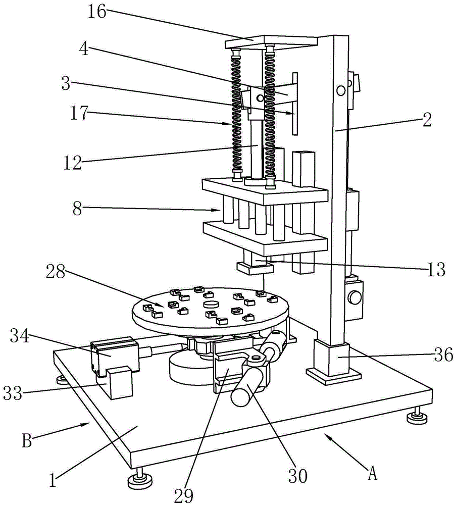
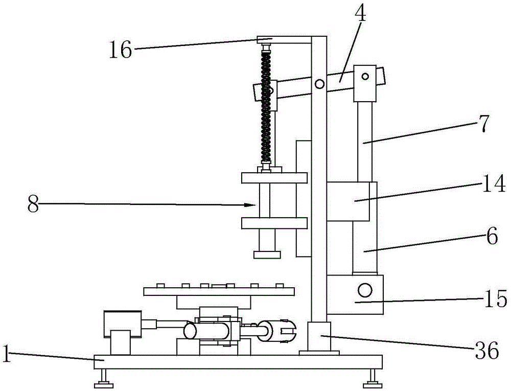
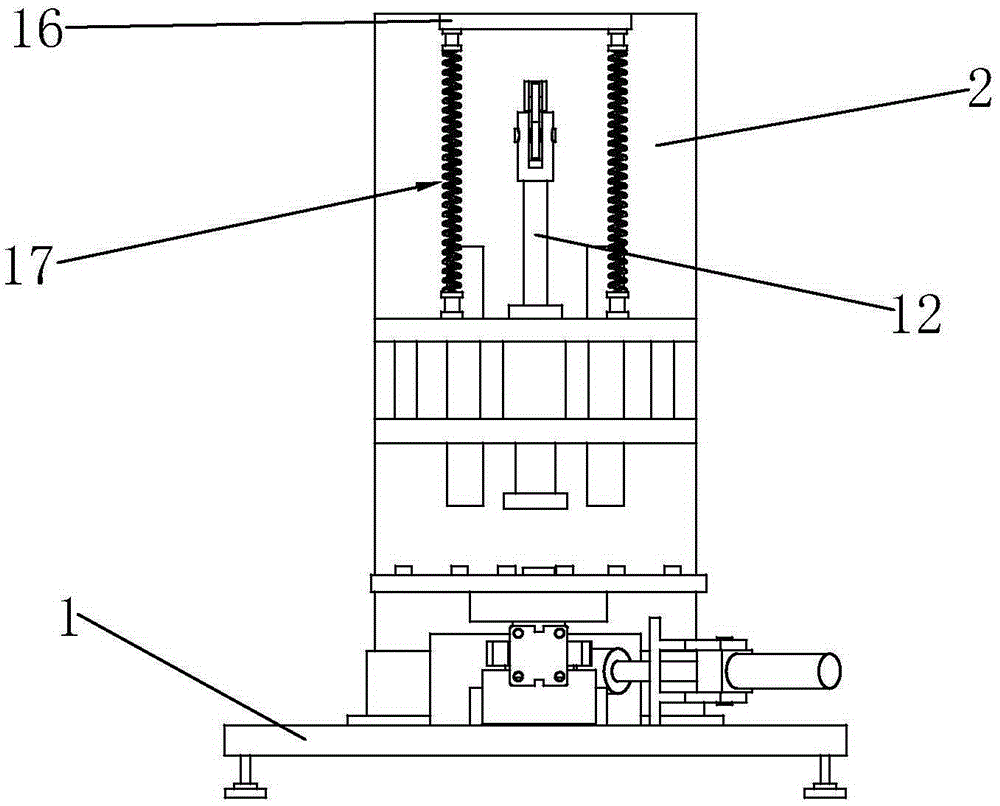
[0028] Such as Figure 1 to Figure 9As shown, it is a stamping equipment applied to the production of motor rotor sheeting according to the present invention, including a mounting base 1 and a supporting frame 2, the supporting frame 2 is arranged on the mounting base 1, and the supporting frame 2 and the mounting base 1 is provided with a reinforcing rib 36 to enhance the stability of the connection between the support frame 2 and the installation base 1. The support frame 2 is p...
PUM
 Abstract
Description
Claims
Application Information