
Multi-machine frequency converter

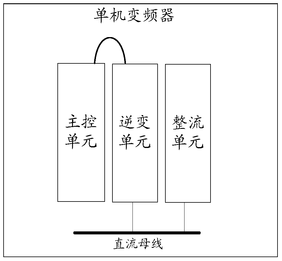
A frequency converter and inverter unit technology, which is used in the control of multiple AC motors, conversion equipment for intermediate conversion to DC conversion, conversion of AC power input to AC power output, etc. The control structure of the master-slave system is complex, the serial bus wiring is too long, etc., to achieve the effect of simple installation and wiring, anti-interference ability, and simplifying the complexity of the wiring structure

Active Publication Date: 2018-02-02
SHENZHEN INVT ELECTRIC
View PDF5 Cites 0 Cited by
  • Summary
  • Abstract
  • Description
  • Claims
  • Application Information

AI Technical Summary

Problems solved by technology

This method of connecting multiple inverters to achieve parallel synchronous operation has problems in field applications, such as the high cost of parallel synchronous operation, complex wiring of various control lines, and too long serial bus wiring
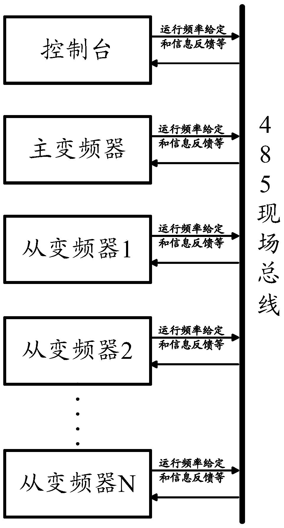
[0004] In the process of research and practice, the inventor found that the existing inverter system has some defects in the application of dual-machine or multi-machine master-slave control: the communication mode of the 485 bus has weak anti-interference in the communication mode between the master and the slave machines. , the disadvantage of poor signal transmission stability
Due to the limitations of communication methods, it is difficult to carry out ultra-long-distance signal transmission
Moreover, the control structure of the master-slave system is complex, multiple signal lines work at the same time, and the installation and operation are cumbersome

Method used


Image

  • Multi-machine frequency converter
  • Multi-machine frequency converter
  • Multi-machine frequency converter

Examples


Embodiment Construction

[0053] The following will clearly and completely describe the technical solutions in the embodiments of the present invention with reference to the accompanying drawings in the embodiments of the present invention. Obviously, the described embodiments are only some, not all, embodiments of the present invention. Based on the embodiments of the present invention, all other embodiments obtained by persons of ordinary skill in the art without making creative efforts belong to the protection scope of the present invention.

[0054] The embodiment of the present invention provides a multi-machine frequency converter, in order to simplify the complexity of the wiring structure in the multi-machine scene of the frequency converter, and improve the stability and reliability of the multi-machine operation of the frequency converter.

[0055] In order to make the purpose, features and advantages of the present invention more obvious and understandable, the technical solutions in the embo...


PUM


Abstract

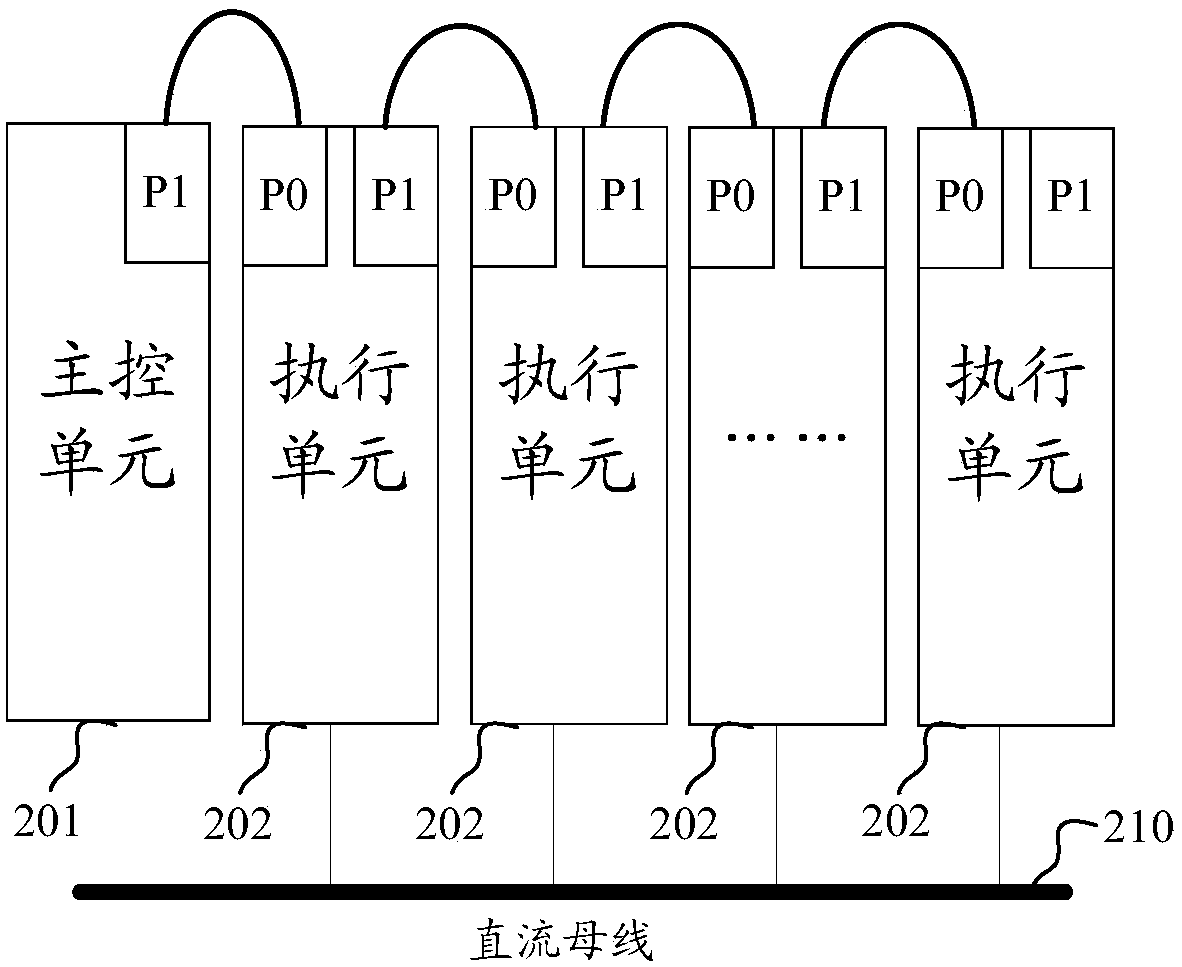
Provided is a multi-machine frequency converter, which may comprise: a master control unit, and N1 execution units coupled in series by means of a communications port, said N1 execution unit sharing a common DC bus; the first communications port of the master control unit is connected to the second communications port of the first of the N1 execution units; the N1 execution units comprise N11 rectifier units and N12 inverter units; N11 is a positive integer, and N12 is a positive integer greater than 1; said first execution unit is an execution unit located at an edge position of said N1 execution units connected in series by means of a communications port. The technical solution provided by the embodiments of the present invention is conducive to reducing the complexity of frequency converter wiring configurations in the context of multiple machines, improving the stability and reliability in multi-machine operation of frequency converters.

Description

technical field [0001] The invention mainly relates to the technical field of power electronics, and in particular relates to a multi-machine frequency converter. Background technique [0002] At present, most inverters on the market are stand-alone inverters, which use a control unit to directly control an inverter unit. The control unit generally does not control the rectification unit. The specific structure can be as follows: Figure 1-a shown. [0003] The stand-alone inverters need to run in parallel synchronously (that is, the speed / torque of the load motors of at least two stand-alone inverters is the same or corresponding, or the outputs of at least two stand-alone inverters are connected in parallel with load motors or asynchronously to realize the factory macro) At the same time, at least two single-machine inverters form an inverter multi-machine system, and the communication between each inverter is based on the RS485 bus. The structure of the 485 bus communica...

Claims


Application Information

Patent Timeline
Patent Type & Authority Patents(China)
IPC IPC(8): G05B19/418H02P5/74
CPCH02M5/00H02M5/42Y02P90/02
Inventor 柯冬生
Owner SHENZHEN INVT ELECTRIC
Learn More