Retaining device for at least one battery cell

一种电池单池、支架元件的技术,应用在电池、电池组零部件、电路等方向,能够解决不可能形状锁合的连接、不可能定位电池单池等问题,达到重量减小、简单制造技术、高拉力负荷的效果

Inactive Publication Date: 2016-03-23
ROBERT BOSCH GMBH
View PDF6 Cites 2 Cited by
  • Summary
  • Abstract
  • Description
  • Claims
  • Application Information

AI Technical Summary

Problems solved by technology

[0003] A disadvantage of the known prior art is that, in order to produce a battery module, the battery cells have to be pressed together by means of high pressing pressure, whereby it is not possible to precisely position the battery cells in order to achieve, for example, a uniform heat dissipation of the battery cells, And thus due to manufacturing tolerances it is not possible to form a form-fitting connection between the holder and the battery cell

Method used


Image

  • Retaining device for at least one battery cell
  • Retaining device for at least one battery cell
  • Retaining device for at least one battery cell

Examples


Embodiment Construction

[0022] In all figures, the same reference numerals refer to the same equipment components.

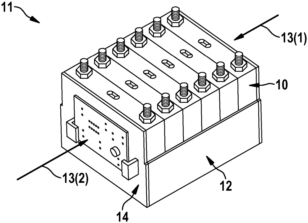
[0023] figure 1 A battery module 11 according to the prior art is shown with, for example, six battery cells 10 , wherein the battery cells 10 are pressed against each other 13 ( 1 ), 13 ( 2 ) under pressure to produce the battery module 11 . ), and the brackets 12 are fixed around the battery cell 10 when pressed against each other. The support can consist, for example, of a plurality of support parts 12 , 14 which are welded to one another. exist figure 1 Among them, the bracket parts 12 and 14 have different heights, for example for stabilizing the battery cell or for fixing the controller on the battery module 11 .

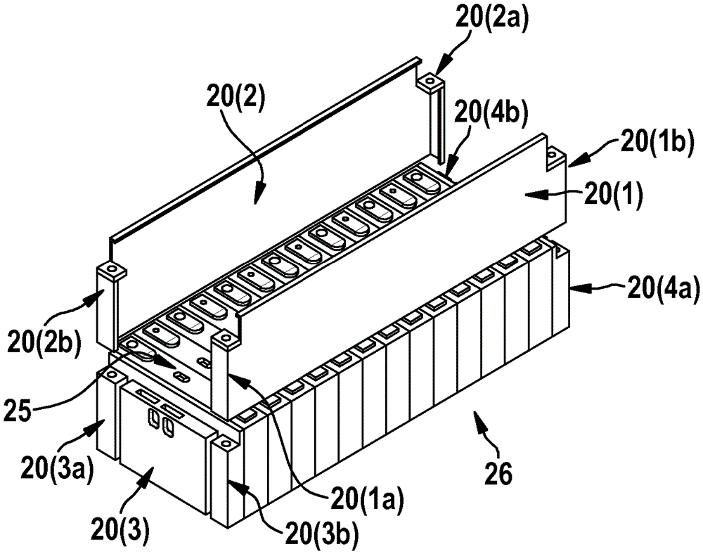
[0024] figure 2 Shown is a battery module 26 with twelve battery cells 25 , which are electrically connected in series with one another by means of cell connectors. In the illustrated embodiment, the stent according to the invention comprises four stent elements ...


PUM


Abstract

The invention relates to a retaining device for at least one battery cell, wherein the retaining device comprises at least two retaining elements, each retaining element comprises at least one fastening means, and the at least two retaining elements are mechanically detachably connected by means of the fastening means.

Description

technical field [0001] The invention relates to a holder for at least one battery cell, the holder comprising at least two holder elements. Background technique [0002] Soldered holders are known from the prior art, and the cells are integrated into the battery module under high compression pressure. [0003] A disadvantage of the known prior art is that, in order to produce a battery module, the battery cells have to be pressed together by means of high pressing pressure, whereby it is not possible to precisely position the battery cells in order to achieve, for example, a uniform heat dissipation of the battery cells, And thus due to manufacturing tolerances it is not possible to produce a positive connection between the carrier and the battery cells. Contents of the invention [0004] On the contrary, the embodiments according to the invention which have the characterizing features of the independent claims have the advantage that the support of the at least one batte...

Claims


Application Information

Patent Timeline
Patent Type & Authority Applications(China)
IPC IPC(8): H01M2/10H01M50/209H01M50/264
CPCH01M2220/20Y02E60/10H01M50/209H01M50/264
Inventor E.赖默C.米勒
Owner ROBERT BOSCH GMBH
Why Eureka
Try Eureka