Waste organic glass crushing device

A plexiglass and crushing device technology, applied in the direction of solid separation, filter screen, grid, etc., can solve the problems of affecting production, long residence time, low crushing efficiency, etc., and achieve the goal of improving work efficiency, reducing crushing cost, and high-efficiency crushing Effect

Inactive Publication Date: 2016-03-30
宁远县致远玻璃制品有限公司
View PDF5 Cites 0 Cited by
  • Summary
  • Abstract
  • Description
  • Claims
  • Application Information

AI Technical Summary

Problems solved by technology

During the crushing process of traditional crushers, blocky plastics will roll up and down in the crusher working chamber, staying for a long time, and cannot be broken into small particles quickly. The crushing efficiency is low, which seriously affects the output. At the same time, blocky plastics are crushing The working room of the crusher rolls up and down and hits the inner wall of the working room of the crusher, which produces a lot of noise and seriously affects the work efficiency of workers.

Method used


Image

  • Waste organic glass crushing device
  • Waste organic glass crushing device

Examples


Embodiment 1

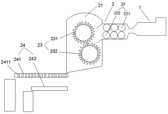
[0019] A crushing device for waste plexiglass, as attached figure 1 As shown, it includes a feed structure 1 and a crushing structure 2. The crushing structure 1 includes a crushing chamber 21, a crushing part 22 arranged in the crushing chamber 21 and a crushing part 23 arranged in the crushing chamber 21 behind the crushing part 22, A screening structure 24 is connected to the rear of the crushing part 23, including a first conveying plate 241 and a second conveying plate 242. The first conveying plate 241 is provided with a sieve hole 2411 with an aperture of 5-10 mm. Above, in this embodiment, the aperture diameter of the sieve is 8mm. Squeeze part 22 comprises upper squeeze roller 221 and the lower squeeze roller 222 opposite with upper squeeze roller 221; Crushing part 23 comprises the first crushing roller 231 and the second crushing roller 232 that arrange up and down, each crushing roller is provided with There are blades, and the blades on the first crushing roller ...

Embodiment 2

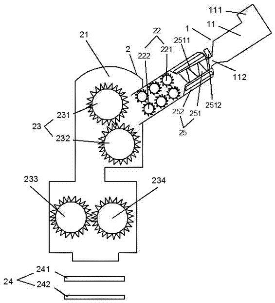
[0021] A crushing device for waste plexiglass, as attached figure 2 As shown, it includes a feed structure 1 and a crushing structure 2. The crushing structure 1 includes a crushing chamber 21, a crushing part 22 arranged in the crushing chamber 21 and a crushing part 23 arranged in the crushing chamber 21 behind the crushing part 22, The feeding structure 1 includes a feeding chamber 11 communicating with the crushing chamber 21 , and the feeding chamber 11 is provided with a feeding port 111 and a flat discharge port section 112 .

[0022] A screening structure 24 is connected to the rear of the crushing part 23, including a first conveying plate 241 and a second conveying plate 242. The first conveying plate 241 is provided with a sieve hole 2411 with an aperture of 5-10 mm. Above, in this embodiment, the aperture diameter of the sieve is 8mm. The extruding part 22 comprises an upper extruding roller 221 and a lower extruding roller 222 relative to the upper extruding rol...


PUM


Abstract

The invention relates to the recycling field of organic glass, in particular to a waste organic glass crushing device which comprises a feeding structure and a crushing structure, wherein the crushing structure comprises a crushing cavity, an extruding part arranged in the crushing cavity and a crushing part which is arranged in the crushing cavity and positioned behind the extruding part; a sieving structure is connected behind the crushing part; the sieving structure comprises a first conveyor plate and a second conveyor plate; the first conveyor plate is positioned above the second conveyor plate; and the first conveyor plate is provided with sieve holes. The waste organic glass crushing device can be used for efficiently crushing the waste organic glass, and is small in noise, so that the working efficiency is improved and the crushing cost is reduced on the premise of guaranteeing complete crushing.

Description

technical field [0001] The invention relates to the field of reutilization of organic glass, in particular to a crushing device for waste organic glass. Background technique [0002] At present, most of the plastic recycling process requires the use of crushers, and the recycled plastics must be put into the crusher to be broken into small particles before further processing. A traditional crusher generally includes a crusher working room, a crushing motor knife installed at the bottom of the crusher working room, a fixed knife set opposite to the crusher machine knife, a feeding port set on the upper part of the crusher working room, and a crusher located under the crusher knife. The discharge mesh plate. During the crushing process of traditional crushers, blocky plastics will roll up and down in the crusher working chamber, staying for a long time, and cannot be broken into small particles quickly. The crushing efficiency is low, which seriously affects the output. At th...

Claims


Application Information

Patent Timeline
Patent Type & Authority Applications(China)
IPC IPC(8): B02C18/14B02C18/18B02C18/22B02C18/16B02C23/10B07B1/46
CPCB02C18/142B02C18/16B02C18/18B02C18/2225B02C23/10B07B1/4609
Inventor 杨小荣孙亚平
Owner 宁远县致远玻璃制品有限公司
Why Eureka
Try Eureka