
Plate rolling machine with cooling function

A plate rolling machine and functional technology, applied in the direction of forming tools, manufacturing tools, metal processing equipment, etc., can solve the problems of fast speed of plate rolling machine, high pressure adjustment of plate rolling machine, poor heat dissipation conditions, etc., to reduce the risk of burnout chance, saving power, good heat dissipation effect

Inactive Publication Date: 2016-03-30
CHONGQING HUTONG PIPELINE TECH EQUIP
View PDF0 Cites 2 Cited by
  • Summary
  • Abstract
  • Description
  • Claims
  • Application Information

AI Technical Summary

Problems solved by technology

At the same time, the pressure adjustment of the plate bending machine is too high, so that the speed of the plate rolling machine becomes very fast, which easily causes the sealing ring and side plate to burn out
Moreover, the oil tank of the bending machine itself is too small, which also makes the heat dissipation condition poor

Method used


Image

  • Plate rolling machine with cooling function
  • Plate rolling machine with cooling function

Examples


Embodiment 1

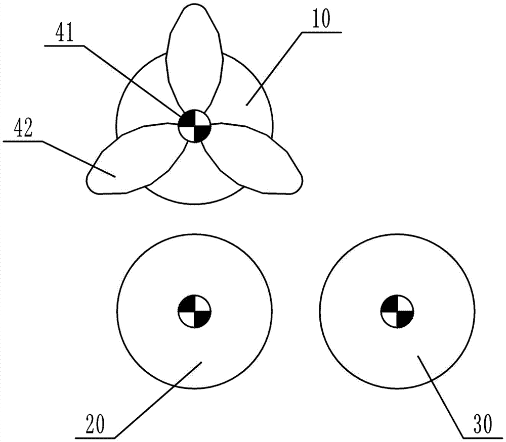
[0017] Such as figure 1 As shown, the plate bending machine with cooling function includes a frame, an upper roller 10, a lower roller 20, an edge roller 30 and a power source for driving the upper roller 10 to rotate. The power source is a servo motor, which is more controllable and has a longer service life than ordinary motors. The upper roller 10, the lower roller 20 and the side roller 30 are all rotatably connected to the frame. In addition, it also includes a first connecting shaft 41 and a first fan blade, the first connecting shaft 41 is coaxially connected with the upper roller 10, and the first fan blade is installed on the first connecting shaft 41. The first fan blade is a plastic fan blade, the cost of the plastic fan blade is low, and the gravity is light, and it is easier to drive the plastic fan blade to rotate.

[0018] During specific work, the steel plate is first placed between the upper roll 10 and the lower roll 20, and the servo motor is started, and the ...

Embodiment 2

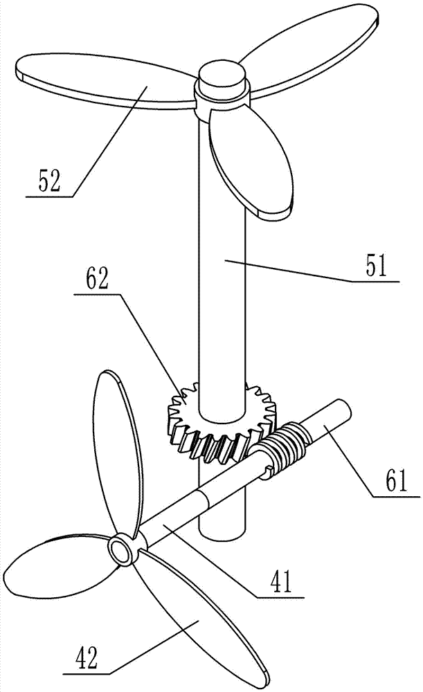
[0021] The difference between this solution and Embodiment 1 is that this solution also includes a worm gear 62, a worm 61 meshing with the worm gear 62, a second connecting shaft 51 and a second fan blade, and the worm 61 is coaxial with the first connecting shaft 41 connection. The worm gear 62 is installed on the second connecting shaft 51, and the second fan blade is installed on the second connecting shaft 51. When the upper roller 10 rotates, the worm 61 is driven to rotate, and the worm 61 drives the worm gear 62 to rotate, thereby prompting the second fan 52 on the second connecting shaft 51 to rotate, and cooling the side of the plate bending machine by blowing air, and the cooling effect is better.


PUM


Abstract

The invention belongs to metal plates bent along the straight line, and particularly discloses a plate rolling machine with the cooling function. The plate rolling machine comprises a rack, an upper roller, a lower roller, a side roller and a power source driving the upper roller to rotate. The upper roller, the lower roller and the side roller are all rotationally connected to the rack. The plate rolling machine further comprises a first connecting shaft and first fan blades. The first connecting shaft is coaxially connected with the upper roller. The first fan blades are installed on the first connecting shaft. According to the scheme, the fan blades are installed on the first connecting shaft, and therefore when the power source drives the upper roller, the fan blades can be driven to rotate without additional power, and electric energy is saved. Meanwhile, when the fan blades rotate, a good cooling effect is achieved, in addition, dust or impurities on rolled plates can be blown away, and a certain cleaning function can be achieved for the rolled plates. Compared with a traditional plate rolling machine, the plate rolling machine in the scheme has a good heat dissipation effect, and the probability of burnout of sealing rings and side plates is effectively reduced.

Description

Technical field [0001] The invention belongs to the bending of a metal plate along a straight line, and in particular relates to a plate bending machine with a cooling function. Background technique [0002] The plate rolling machine is a shaping machine for continuous point bending of plates, and has the function of rolling O-shaped, U-shaped, multi-segment R and other shapes of plates. Because of the different fields of use, the types of bending machines are also different. From the number of rollers, it is divided into three-roller and four-roller. The most commonly used is the three-roller plate bending machine, which mainly includes the upper roller, the lower roller and the side roller. The upper roller is the main driving roller and is connected with the power source. The lower roller moves vertically to clamp the plate and pass through the lower roller gear. It meshes with the upper roller gear; the side roller moves up and down, with dual functions of pre-bending and r...

Claims


Application Information

Patent Timeline
Patent Type & Authority Applications(China)
IPC IPC(8): B21D5/14B21D37/16
CPCB21D5/14B21D37/16
Inventor 张永雄
Owner CHONGQING HUTONG PIPELINE TECH EQUIP
Learn More