Expanding mould type bidirectional turning clamp

A car fixture and tire expansion technology, which is applied in the field of clamping devices for motor stator iron cores, can solve the problems of looseness between the teeth of the iron core, difficulty in picking parts, and aggravating the labor intensity of the operator, so as to achieve smooth separation and closing. The effect of convenient clamping

Inactive Publication Date: 2016-03-30
SUZHOU INST OF INDAL TECH
View PDF4 Cites 6 Cited by
  • Summary
  • Abstract
  • Description
  • Claims
  • Application Information

AI Technical Summary

Problems solved by technology

However, the above-mentioned technical solution has the following technical defects: although the product quality of the fixture is relatively ideal, a strong self-locking force is produced after the outer cone surface of the mandrel cooperates with the inner hole of the stator, which makes it difficult to pick up the part after turning, and the mandrel must be thrown many times The small end face can be loosened and demolded
Such an operation not only increases the labor intensity of the operator, but also may cause loosening between the teeth of the iron core.

Method used


Image

  • Expanding mould type bidirectional turning clamp
  • Expanding mould type bidirectional turning clamp
  • Expanding mould type bidirectional turning clamp

Examples


Embodiment Construction

[0031] The present invention will now be further described in detail in conjunction with the accompanying drawings and embodiments. These drawings are all simplified schematic diagrams, only illustrating the basic structure of the present invention in a schematic manner, so it only shows the composition related to the present invention.

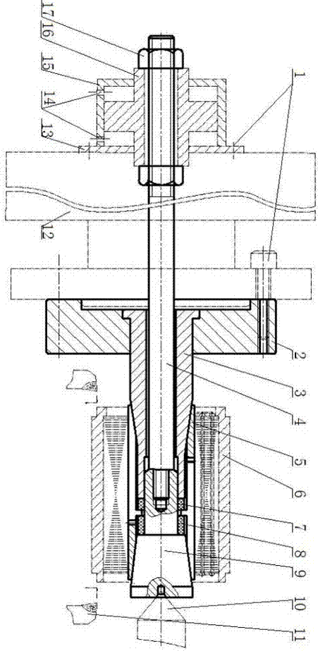
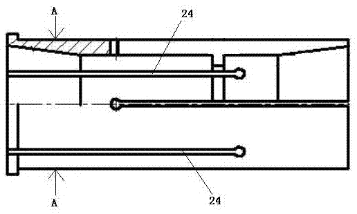
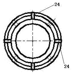
[0032] Such as Figure 1-5 As shown, a tire-expanding two-way vehicle fixture includes: an elastic chuck 5, and a taper sleeve 3 and a mandrel 9 both sleeved in the elastic chuck 5, and the outer circumference of the taper sleeve 3 and the mandrel 9 are tapered , one end of the small end of the taper sleeve 3 and one end of the small end of the mandrel 9 are respectively provided with matching nesting heads, and the nesting heads of the taper sleeve 3 and the mandrel 9 are inserted from the two ends of the elastic chuck 5 respectively, and are The clips 5 are nested together, and the inner wall of the elastic clip 5 near the two ends of the e...


PUM


Abstract

The invention relates to an expanding mould type bidirectional turning clamp. The expanding mould type bidirectional turning clamp comprises an elastic clamping cylinder, a conical sleeve and a mandrel, wherein the conical sleeve and the mandrel are both sleeved by the elastic clamping cylinder, and the peripheries of the conical sleeve and the mandrel have conicity. The expanding mould type bidirectional turning clamp is characterized in that mutually-matched nesting heads are arranged at the smaller end of the conical sleeve and the smaller end of the mandrel respectively, the nesting heads of the conical sleeve and the mandrel are respectively sleeved from the two ends of the elastic clamping cylinder and are mutually nested together in the elastic clamping cylinder, and the structures, close to the two end positions of the elastic clamping cylinder, of the inner wall of the elastic clamping cylinder are respectively matched with the structures of the peripheries of the conical sleeve and the mandrel. The expanding mould type bidirectional turning clamp further comprises a pull rod sleeved in the inner cavity of the conical sleeve, wherein the pull rod penetrates through the conical sleeve and then is detachably connected to the mandrel. Compared with a small-conicity core rod turning clamp, the dual-expanding clamping cylinder type turning clamp has the advantages of being convenient to operate, efficient and high in finished product rate. It can be considered that the successfully used structure can be effectively popularized for machining of sleeve type parts having similar demands.

Description

technical field [0001] The invention relates to a clamping device for a stator iron core of a motor, in particular to a tire-expanding type two-way vehicle clamp. Background technique [0002] The low-speed permanent magnet synchronous motor can directly obtain a lower speed above 60r / min without a mechanical reduction mechanism, and has a higher torque (3000mN·m) and better self-locking ability. The stator as the core component of the motor is the key to obtaining these excellent technical indicators, so it is particularly important to ensure the quality of the stator core and the stator shell after turning. [0003] The stator core is formed by stacking multiple stator punches with rivets, and the riveted stator core is interference-fitted into the casing by the shrink-fit method (at this time, only the seams at both ends of the casing are reserved 0.5mm margin for finish turning, that is, rough turning to Φ72.5). [0004] The laminated stator core needs to be pressed in...

Claims


Application Information

Patent Timeline
IPC IPC(8): B23B31/40
CPCB23B31/4053
Inventor 肖洪波殷铭
Owner SUZHOU INST OF INDAL TECH
Why Eureka
Try Eureka