An obstacle detection car and its operation method

An obstacle detection and obstacle technology, applied in railway inspection vehicles and other directions, can solve the problems of increased construction workers, operator burnout, operator burnout and negligence, etc., so as to avoid the phenomenon of over-limit operation, improve the degree of automation, operation and safety. The effect of convenient transportation

Active Publication Date: 2017-12-15
ZHUZHOU TIMES ELECTRONICS TECH CO LTD +1
View PDF6 Cites 0 Cited by
  • Summary
  • Abstract
  • Description
  • Claims
  • Application Information

AI Technical Summary

Problems solved by technology

[0003] The complexity and safety requirements of the construction of current railway lines, especially high-speed railway lines, the number of construction workers continues to increase, and the cost of line maintenance has also doubled
Since the existing railway engineering operations mainly rely on manual observation to ensure over-limit early warning during the construction process, this manual method absolutely depends on the responsibility of the personnel themselves, especially when the maintenance tasks of railway lines are heavy, the operators will inevitably experience burnout and negligence This can easily lead to safety accidents in railway construction
In the construction process of many railway lines in the past, there have been frequent occurrences of burnout of operators, resulting in more serious safety accidents of line equipment, such as serious construction accidents such as the occurrence of serious construction accidents such as screen cleaners hitting catenary poles

Method used


Image

  • An obstacle detection car and its operation method
  • An obstacle detection car and its operation method
  • An obstacle detection car and its operation method

Examples


Embodiment Construction

[0035] In order to make the purpose, technical solutions and advantages of the embodiments of the present invention more clear, the technical solutions in the embodiments of the present invention will be clearly and completely described below in conjunction with the drawings in the embodiments of the present invention. Apparently, the described embodiments are only some of the embodiments of the present invention, not all of them. Based on the embodiments of the present invention, all other embodiments obtained by persons of ordinary skill in the art without creative efforts fall within the protection scope of the present invention.

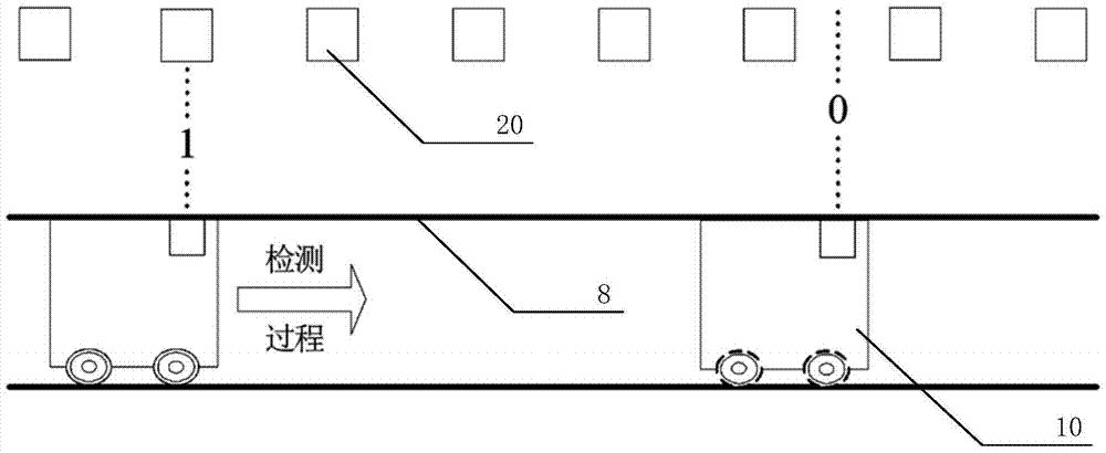
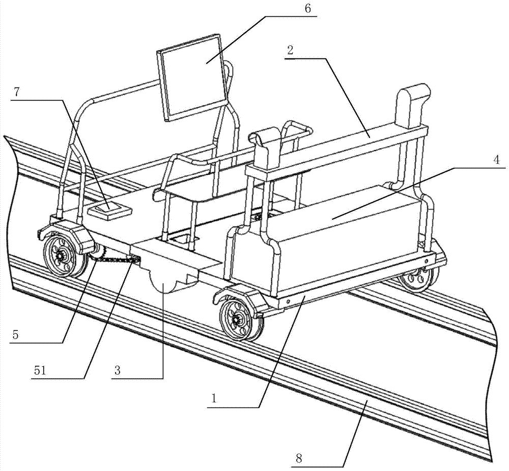
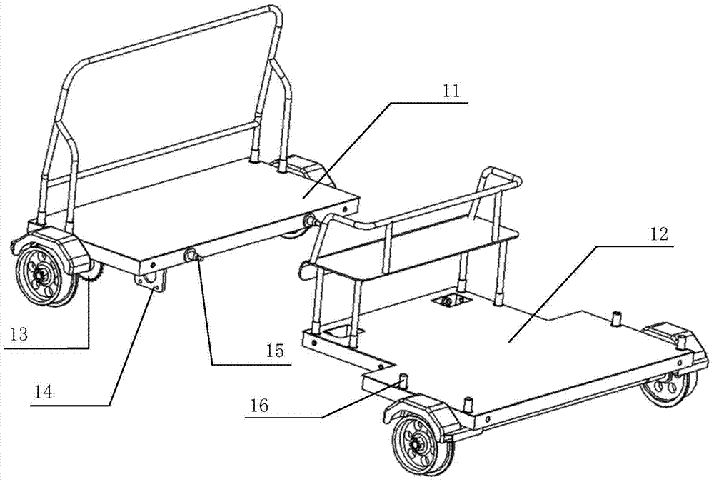
[0036] as attached figure 1 to attach Image 6 As shown, specific embodiments of the obstacle detection trolley and its working method of the present invention are given, and the present invention will be further described below in conjunction with the accompanying drawings and specific embodiments.

[0037] as attached figure 2 As shown, a s...


PUM


Abstract

The invention discloses an obstacle detecting trolley and an operation method thereof. The trolley comprises a trolley body module, a measurement module, a mileage module, a control module, a power module and a display module. The trolley body module is used as the body of the obstacle detecting trolley and used for bearing the measurement module, the mileage module, the control module, the power module and the display module. The measurement module detects the distance of obstacles on the two sides of a rail. The mileage module measures travel mileage data of the obstacle detecting trolley. The control module receives obstacle distance information acquired by the measurement module and the travel mileage data of the trolley, acquired by the mileage module, and forms a correspondence table to be sent to large railway maintenance machine self-wheel running equipment. The power module provides power for the obstacle detecting trolley. The display module is used in the operation process of the obstacle detecting trolley and used for displaying the process of data sending to the large road maintenance machine self-wheel running equipment. By means of the obstacle detecting trolley and the operation method thereof, the requirement of the large railway maintenance machine self-wheel running equipment for safe operation can be met, and safety of railway operation lines, constructors and equipment is guaranteed.

Description

technical field [0001] The invention relates to the field of railway engineering, in particular to an obstacle detection trolley and an operation method thereof which are applied to large-scale road maintenance machinery running on wheels (such as a ballast truck and a screen cleaning truck, etc.). Background technique [0002] In the prior art, the working mechanism of the large-scale railway maintenance machinery self-wheeling operation equipment (mainly including: ballast truck and screen cleaning truck) usually exceeds the limit during the construction process. At present, in the actual construction safety management process of large-scale railway maintenance machinery in China, the main method for over-limit phenomena that may occur during the construction operation is to rely entirely on the operator to monitor the operation safety manually, and to ensure the construction through manual observation. Job security. [0003] Due to the complexity and safety requirements ...

Claims


Application Information

Patent Timeline
Patent Type & Authority Patents(China)
IPC IPC(8): B61D15/12
CPCB61D15/12
Inventor 何为国颜琼陈平松李懿
Owner ZHUZHOU TIMES ELECTRONICS TECH CO LTD
Why Eureka
Try Eureka