
A space transmission system that maintains continuous delivery

A space transmission and continuous technology, applied in the system field, can solve the problems of shortened conveying distance, large installation space, and large space occupation, and achieve the effect of shortening conveying distance, saving installation area and higher safety.

Active Publication Date: 2017-10-24
SICHUAN DEYANG NIANFENG FOOD
View PDF6 Cites 0 Cited by
  • Summary
  • Abstract
  • Description
  • Claims
  • Application Information

AI Technical Summary

Problems solved by technology

[0003] The purpose of the present invention is to overcome the problem that the above-mentioned existing conveying mechanism occupies a large space for installation, and the conveying belt is easily damaged due to the pressure of the goods during conveying. After a long time of use, the internal structure swings greatly, resulting in damage and unable to work continuously. A space transmission system that maintains continuous transportation. The system is designed as a spiral transportation, which can save the installation area, realize vertical transportation in space, shorten the transportation distance, and reduce the collision with other components by limiting the position of the internal structure. The damage caused by it makes it possible to work continuously, and the conveying speed can be kept consistent, so that the safety of the conveying is higher, and the efficiency of the conveying is improved, which solves the problem that the existing conveying mechanism occupies a large space due to the pressure of the article during conveying. The transmission belt is easy to be damaged, and the internal structure swings greatly after long-term use, causing damage and unable to work continuously

Method used


Image

  • A space transmission system that maintains continuous delivery
  • A space transmission system that maintains continuous delivery

Examples


Embodiment

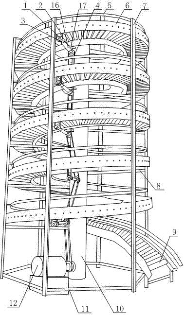
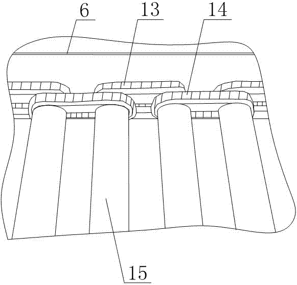
[0013] Such as figure 1 , figure 2 As shown, a space transmission system that maintains the continuity of transportation includes a column 10, the outer wall of the column 10 is provided with a screw conveying mechanism 9, and the screw conveying mechanism 9 is wound around the outer wall of the column 10, and the two sides of the screw conveying mechanism 9 The ends corresponding to the columns 10 are arranged at the same level. The screw conveying mechanism 9 is mainly composed of two spiral belts 6 arranged in parallel at the same height. Several rollers 15 are arranged between the spiral belts 6. The two ends of the roller 15 pass through the corresponding spiral belt 6 respectively, and the roller 15 can rotate in the spiral belt 6 around their respective axes, and a gear is fitted on the outer wall of the roller 15, and two adjacent rollers 15 form each The roller group, the roller 15 in the roller group is provided with a chain one 14, and the chain one 14 is meshed w...


PUM


Abstract

The invention discloses a space transmission system capable of keeping conveying continuity. A spiral conveying mechanism is arranged on the outer wall of a stand column, and a plurality of rollers are arranged between spiral belts. The outer walls of the rollers are sleeved with gears. Every two adjacent rollers form a respective roller set. A first chain and a second chain are arranged on the rollers in each roller set. A motor is arranged on the bottom end face of the stand column. An adjusting structure is arranged below each ring formed by spiraling of the spiral conveying mechanism, the outer wall of each rotary shaft is sleeved with a sleeve, fixed plates are arranged on the outer walls of the sleeves, and the fixed plates are fixed with the outer walls of the sleeves and the stand column. The system is designed to achieve spiral conveying, and perpendicular conveying is achieved in space, so that the conveying distance is shortened. An inner structure is subjected to position limiting, damage caused by the collision of the space transmission system with other components is reduced, the space transmission system can continuously work, and conveying speed can be kept consistent. In the conveying process, higher safety is achieved, and conveying efficiency is improved.

Description

technical field [0001] The invention relates to a system, in particular to a space transmission system that maintains continuity of transportation. Background technique [0002] Conveyors have a long history. In ancient China, high-drum cars and water-lifting rollovers are used. Conveyors are material handling machinery that continuously transport materials on a certain line, also known as continuous conveyors. The conveyor has a large conveying capacity, a long transportation distance, and can complete several process operations at the same time during the conveying process, so it is widely used. According to the different places of use, working environment, technical performance and types of conveying materials of the belt conveyor, in order to meet the forms of various operating conditions, in addition to the more commonly used general belt conveyors, there are also a variety of new types Structure of special belt conveyors, the representative ones are: large-inclination...

Claims


Application Information

Patent Timeline
Patent Type & Authority Patents(China)
IPC IPC(8): B65G13/07B65G13/11
CPCB65G13/07B65G13/11B65G2207/24
Inventor 王安体王长严
Owner SICHUAN DEYANG NIANFENG FOOD
Learn More