Reducing agent delivery unit of liquid cooling of selective catalytic reduction system of motor vehicle

A technology of liquid cooling and reducing agent, which is applied in the direction of engine components, machines/engines, mechanical equipment, etc., and can solve problems such as high heat

Inactive Publication Date: 2016-03-30
CONTINENTAL AUTOMOTIVE SYST INC
View PDF0 Cites 6 Cited by
  • Summary
  • Abstract
  • Description
  • Claims
  • Application Information

AI Technical Summary

Problems solved by technology

[0005] However, this close proximity can re...

Method used


Image

  • Reducing agent delivery unit of liquid cooling of selective catalytic reduction system of motor vehicle
  • Reducing agent delivery unit of liquid cooling of selective catalytic reduction system of motor vehicle
  • Reducing agent delivery unit of liquid cooling of selective catalytic reduction system of motor vehicle

Examples


Embodiment Construction

[0018] The following description of the preferred embodiment(s) is merely exemplary in nature and is in no way intended to limit the invention, its application or uses.

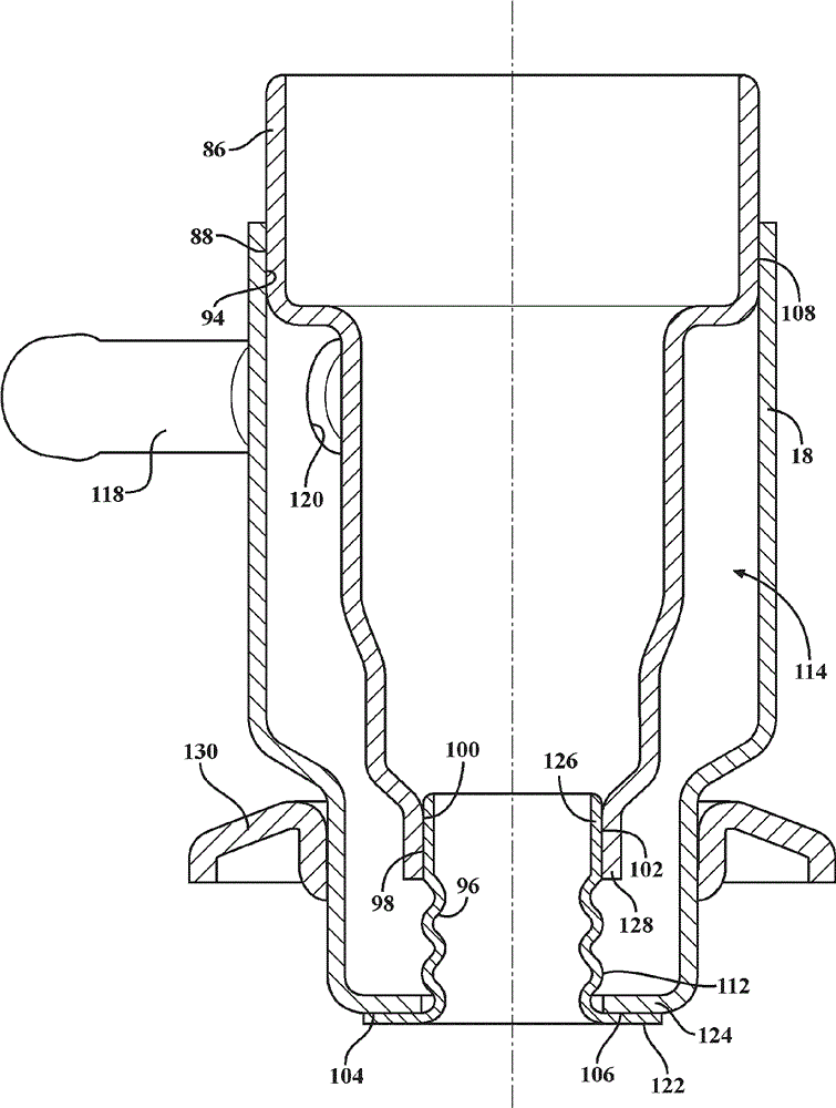
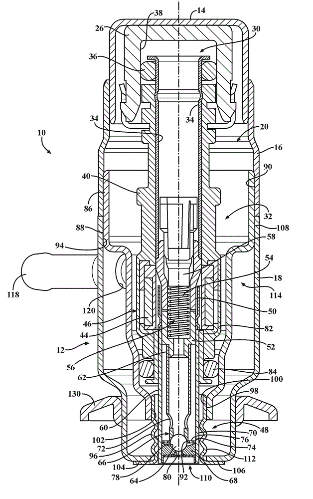
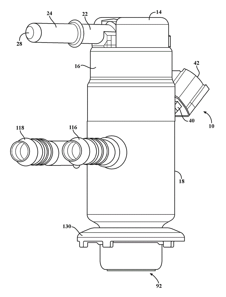
[0019] see Figure 1-3 , an embodiment of an actively cooled reductant delivery unit for an automotive selective catalytic reduction (SCR) system is shown generally at 10 . The reductant delivery unit 10 includes an outer housing or housing, shown generally at 12, and the housing 12 includes a retaining cap 14 connected to an upper shroud 16 and a lower shroud 18, the lower shroud 18 also Connects to upper shroud 16. The retaining cap 14 and housings 16, 18 when connected together form a cavity, shown generally at 20, within which the various components are disposed.

[0020] Cap 14 at least partially surrounds hydraulic connector 22 . The hydraulic connector 22 has an inlet tube 24 and an inlet cup 26 which in this embodiment are integrally formed together, but which may be formed separately within the sc...


PUM


Abstract

The invention discloses a reducing agent delivery unit with an active cooling function. According to the reducing agent delivery unit, the structural stability is high enough, the corrosion resistance of components is improved, and the situation that a base ejector is corroded due to the utilization of incorrect cooling agent media is avoided. The reducing agent delivery unit is provided with an upper protection cover, a lower protection cover connected to the upper protection cover, and an inner sleeve and further comprises a lower sleeve which is connected to the inner sleeve and the lower protection cover. A liquid cooling cavity is formed through the connection between the inner sleeve and the lower protection cover, the connection between the lower sleeve and the lower protection cover as well as the connection between the lower sleeve and the inner sleeve. Cooling agents flow into the liquid cooling cavity and provide a cooling function for an ejector which is partially located in the inner sleeve. In addition, a corrugated part of the lower sleeve is used for transferring and dissipating heat away from at least part of the ejector.

Description

technical field [0001] The present invention generally relates to providing active cooling for a reductant delivery unit for an automotive selective catalytic reduction system. Background technique [0002] New emissions regulations in Europe and North America are driving the implementation of new exhaust aftertreatment systems, especially for applications such as compression-ignition (diesel) engines and stratified-charge spark-ignition engines (typically Lean burn technology using direct injection). Lean-burn engines exhibit high nitrogen oxide (NOx) emission levels, which are difficult to manage in the oxygen-rich exhaust environment characteristic of lean-burn combustion. Exhaust aftertreatment technologies are currently being developed to treat NOx under such conditions. [0003] One of these techniques involves favoring ammonia (NH 3 ) reacts with exhaust nitrogen oxides (NOx) to produce nitrogen (N 2 ) and water (H 2 O) catalyst. The technology is called Selecti...

Claims


Application Information

Patent Timeline
IPC IPC(8): F01N3/28F01N3/20
CPCY02A50/20Y02T10/12
Inventor S.C.布戈斯W.N.范武伦
Owner CONTINENTAL AUTOMOTIVE SYST INC
Why Eureka
Try Eureka