Constant-velocity joint

一种等速接头、接触区的技术,应用在速接头领域,能够解决滑动阻力增加等问题

Active Publication Date: 2016-03-30
HONDA MOTOR CO LTD
View PDF8 Cites 4 Cited by
  • Summary
  • Abstract
  • Description
  • Claims
  • Application Information

AI Technical Summary

Problems solved by technology

[0005] If the roller is inclined in a following relationship with respect to the inclination of the holder, slippage occurs between the wall surface of the guide groove and the roller, thereby resulting in an increase in sliding resistance

Method used


Image

  • Constant-velocity joint
  • Constant-velocity joint
  • Constant-velocity joint

Examples


Embodiment Construction

[0028] Hereinafter, a constant velocity joint according to a preferred embodiment of the present invention will be described in detail with reference to the accompanying drawings.

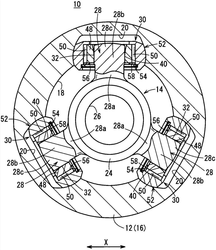
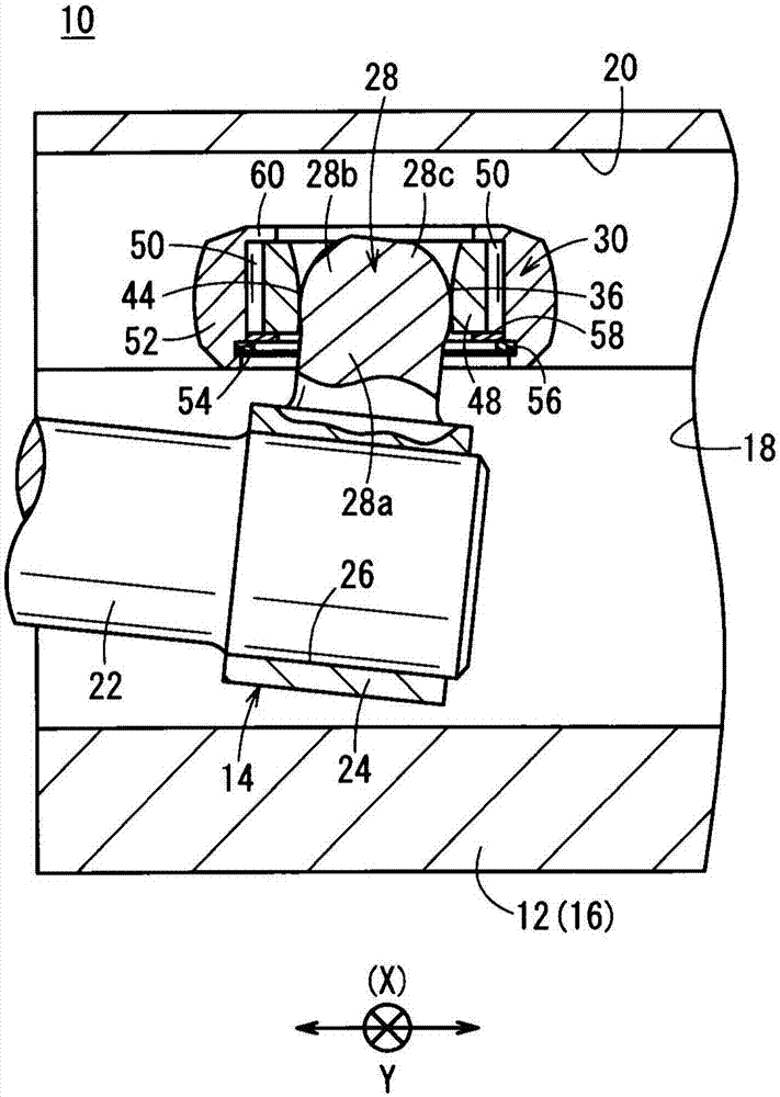
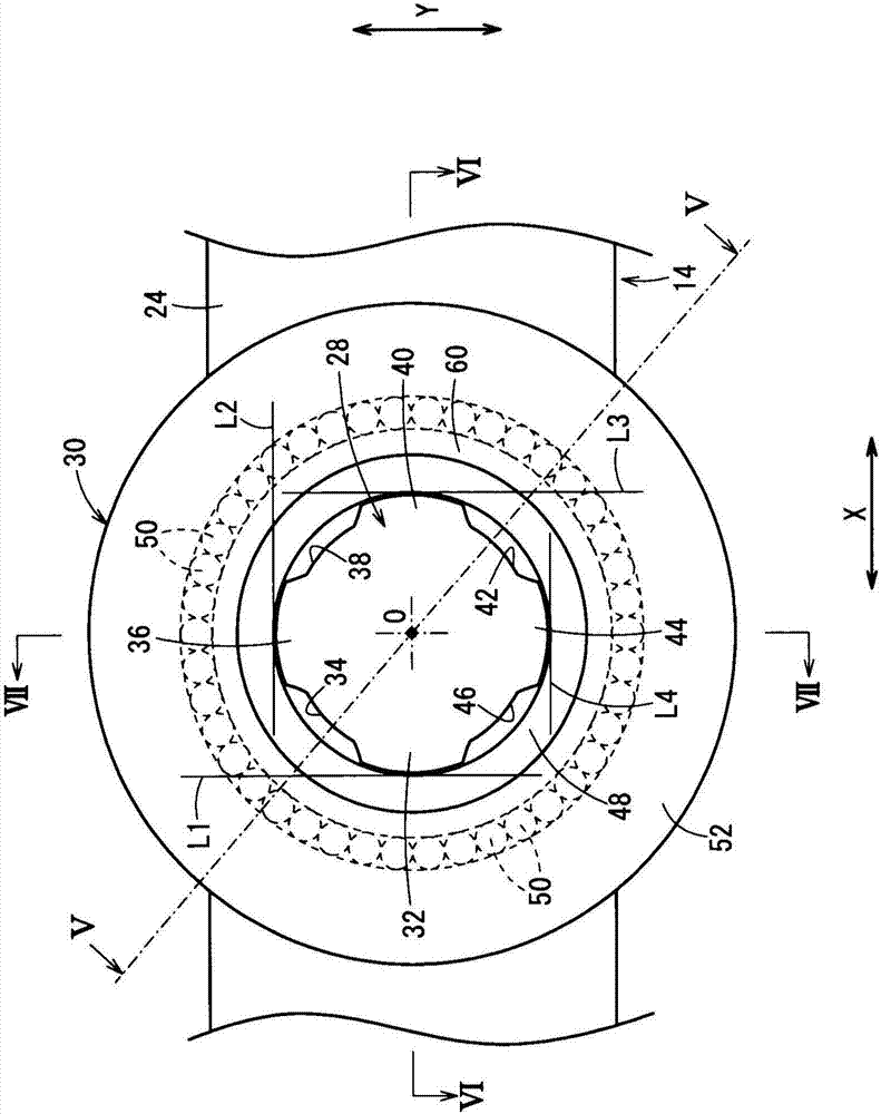
[0029] figure 1 A constant velocity joint 10 according to an embodiment of the invention is shown in cross section, the view being taken along a line perpendicular to the axial direction of the constant velocity joint. figure 2 The constant velocity joint is shown in a fragmentary sectional side view along the axial direction of the constant velocity joint. exist figure 1 , arrow X indicates the width direction or lateral direction of the outer member 12 . exist figure 2 , arrow Y indicates the longitudinal direction of the constant velocity joint 10 . The X direction and the Y direction are perpendicular to each other.

[0030] The constant velocity joint 10 includes an outer member 12 and an inner member 14 . The outer member 12 has a bottomed cup portion 16 and an unillustrated shaft pro...


PUM


Abstract

In a constant-velocity joint (10), an inner member (14) thereof includes holders (28) that serve to retain respective roller assemblies (30). When each of the holders (28) is hypothetically divided into three equal parts made up of a proximal end portion (28a), an intermediate portion (28b), and a distal end portion (28c) from a side of an annular member (24), an inner wall surface of an inner roller (48) of the roller assembly (30) contacts only a side wall surface of the proximal end portion (28a). The inner roller (48) preferably has an inside diameter, which is minimum at a contact point that contacts the side wall surface of the proximal end portion (28a). More specifically, the inside diameter of the inner roller (48) gradually expands in diameter from the contact point to a side that faces toward the annular member (24), and further, gradually expands in diameter from the contact point to a side that faces toward the distal end portion (28c).

Description

technical field [0001] The present invention relates to a constant velocity joint interposed between a first transmission shaft and a second transmission shaft for transmitting rotational driving power from the first transmission shaft to the second transmission shaft. Background technique [0002] Motor vehicles are arranged to transmit rotational drive power generated by an internal combustion engine, electric motor, etc. to tires through a drive power transmission shaft such as a drive shaft or the like. In this case, the motor vehicle is driven while the tire is rotated by the transmitted rotational driving power. [0003] A constant velocity joint is interposed between the driving power transmission shafts. Constant velocity joints interconnect the drive drive shafts such that the drive drive shafts can rotate about their respective axes. [0004] One known type of constant velocity joint is the three-leg type constant velocity joint. The tripod constant velocity joi...

Claims


Application Information

Patent Timeline
Patent Type & Authority Applications(China)
IPC IPC(8): F16D3/205
CPCF16D3/2055F16D2003/2026Y10S464/905
Inventor 辻本史彦
Owner HONDA MOTOR CO LTD
Why Eureka
Try Eureka