Selfie stick structure
A Selfie stick and bracket structure technology, applied in the field of photographic equipment, can solve the problems of difficult operation, easy shaking, occupying space, etc., and achieve the effect of fast and convenient unfolding, compact overall structure, and convenient storage or unfolding.
- Summary
- Abstract
- Description
- Claims
- Application Information
AI Technical Summary
Problems solved by technology
Method used
Image
Examples
Embodiment 1
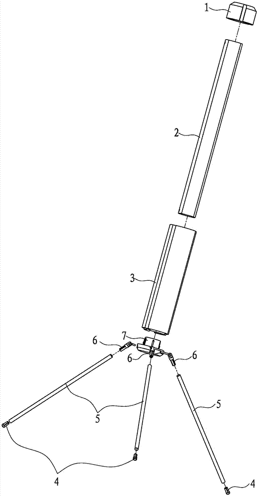
[0066] Cooperate figure 1 As shown, the bracket structure includes an upper cover 1, an outer cover 3 and a lower cover 7 which are set on the casing 2, and also includes three foot pads 4, three round pipes 5, three hinged joints 6 and three pins 8,.
[0067] Strictly speaking, the shape of the sleeve 2 is an oblate tube, and there are two concave planes 211 oppositely arranged on its outer peripheral surface 21 and parallel to its axis, and a slot 271 is opened at the lower end of the two planes 211 .
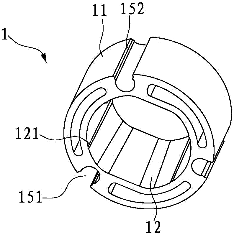
[0068] Cooperate figure 2 As shown, the short round tubular upper cover 1 has three U-shaped slots 151 parallel to its axis evenly distributed on its outer peripheral surface 11, and the two side walls of each U-shaped slot 151 are provided with inwardly facing Raised ribs 152. The inner hole 12 of the upper cover 1 corresponds to the outer peripheral surface 21 of the casing 2; the inner hole 12 of the upper cover 1 is provided with a plurality of ribs 121 parallel ...
Embodiment 2
[0079]The support structure includes an upper cover 21' at one end of the casing 2', a lower cover 22' and a base 23' at the other end; three slots 231' are evenly distributed on the base 23' and three legs are hinged 3'; the bottom of the base 23' is provided with a button 232', and the button 232' drives a limiter 233' to switch between the first position and the second position to form a position when the leg 3' is folded and unfolded. Positioning mechanism, when the limiter 233' is at the first position, the hinged end of the leg 3' is against the limiter 233'; when the limiter 233' is at the second position , the hinged end of the leg 3' is separated from the limiting member 233'.
[0080] When the button is pressed, the rotating shaft of the limiting member 233' and the supporting foot 3' is disengaged, and the supporting foot 3' can rotate freely, so that the 3' can be changed from the stowed state to the opened state, or from the opened state to the stowed state. When...
Embodiment 3
[0090] The support structure includes a lock sleeve 2'' fixed on the sleeve 1'', a sliding sleeve 3'' located below the lock sleeve 2'' and movable with the lock sleeve 2'', and a The expansion spring 4'' between the sliding sleeve 3'' and the locking sleeve, the three legs 5'' whose tops are pivotally connected to the locking sleeve 2'', the three legs whose one end is pivotally connected to the sliding sleeve 3'', and the other end The ejector rods 6'' are respectively pivotally connected to the legs 5''; in addition, a limit mechanism is provided at the lower part of the casing 1'' to prevent the sliding sleeve 3'' from slipping out.
[0091] Cooperate Figure 31 As shown, the lock sleeve 2'' is a sleeve body fixed on the sleeve 1'', which is formed with a cavity for accommodating the following sliding sleeve 3'' from bottom to top, and its upper part is radially provided with Matching hole 21'' to match elastic lock block 7'' (see Figure 28 shown), and the lower par...
PUM
 Abstract
Description
Claims
Application Information
 - R&D
- Intellectual Property
- Life Sciences
- Materials
- Tech Scout
- Unparalleled Data Quality
- Higher Quality Content
- 60% Fewer Hallucinations
Browse by: Latest US Patents, China's latest patents, Technical Efficacy Thesaurus, Application Domain, Technology Topic, Popular Technical Reports.
© 2025 PatSnap. All rights reserved.Legal|Privacy policy|Modern Slavery Act Transparency Statement|Sitemap|About US| Contact US: help@patsnap.com


