Pressure relief device and air conditioner provided with pressure relief device

A technology of pressure relief device, pressure relief tank, applied in the direction of home appliance, container filling method, space heating and ventilation

Inactive Publication Date: 2016-03-30
GREE ELECTRIC APPLIANCES INC
View PDF6 Cites 3 Cited by
  • Summary
  • Abstract
  • Description
  • Claims
  • Application Information

AI Technical Summary

Problems solved by technology

[0004] The main purpose of the present invention is to provide a pressure relief device and an air conditioner with it, so as to solve the problem in the prior art that the fusible plug can only be opened by temperature control

Method used


Image

  • Pressure relief device and air conditioner provided with pressure relief device
  • Pressure relief device and air conditioner provided with pressure relief device
  • Pressure relief device and air conditioner provided with pressure relief device

Examples


Embodiment 1

[0041] The pressure relief device in Embodiment 1 is divided into three working states:

[0042] 1. Normal working status:

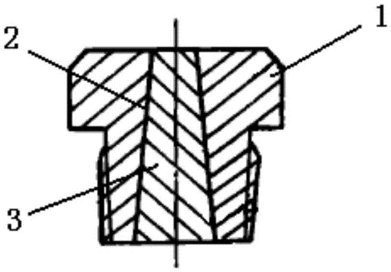
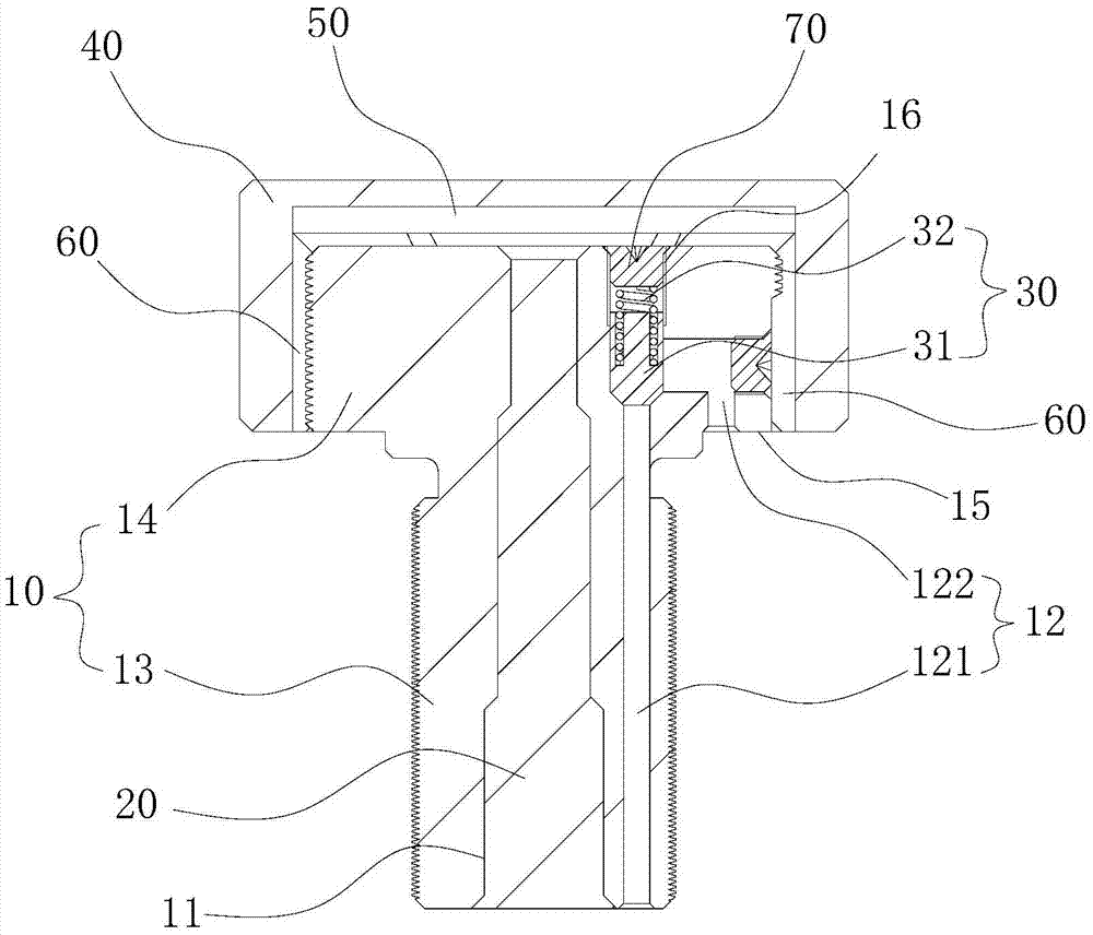
[0043] Such as figure 2 As shown, when the air conditioner unit is working normally, the operating pressure in the pressure vessel and the temperature of the refrigerant do not exceed the standard. At this time, the fusible alloy 20 has no physical state change, the blocking member 30 is in the blocking position, and the refrigerant is sealed in the In the piping system, the refrigerant runs normally in the piping system.

[0044] 2. High temperature working condition:

[0045] Such as Figure 7 and Figure 8 As shown, when the air conditioner unit operates abnormally (or the ambient temperature is extremely high), the temperature of the refrigerant in the pressure vessel is too high, and there is a risk of explosion in the unit piping system or compressor system, at this time, the fusible alloy 20 melts and flows, and high-temperature refrigeration...

Embodiment 2

[0048] The main difference between the pressure relief device of Embodiment 2 and Embodiment 1 is that the first pressure relief channel is curved and the outlet of the first pressure relief channel is located on a stepped surface (not shown in the figure). The above-mentioned structure directly processes the bent first pressure relief channel in the matrix, and makes the outlet of the first pressure relief channel on the step surface, which can also change the outflow direction of the medium and prevent the high temperature medium from directly spraying out. However, compared with the pressure relief device in Embodiment 1, the pressure relief device with the above-mentioned first pressure relief channel is not easy to process and has poor flexibility in use.

[0049] The present application also provides an air conditioner, and an embodiment of the air conditioner according to the present application includes a pressure relief device. The pressure relief device is the above ...


PUM


Abstract

The invention provides a pressure relief device and an air conditioner provided with the pressure relief device. The pressure relief device comprises a base body (10), wherein the base body (10) is provided with a first pressure relief channel (11); the first pressure relief channel (11) is internally provided with a fusible alloy (20) plugging the first pressure relief channel (11); the base body (10) is further provided with a second pressure relief channel (12); the second pressure relief channel (12) is internally provided with a plugging piece (30); the plugging piece (30) is in a plugging position plugging the second pressure relief channel (12) in a free state; and when pressure in the second pressure relief channel (12) reaches a predetermined value, the plugging piece (30) is in a pressure relief position avoiding the second pressure relief channel (12). With the adoption of the technical scheme, the problem that a fusible plug can only be opened by temperature control in the prior art can be solved effectively.

Description

technical field [0001] The present invention relates to the technical field of pressure relief devices, in particular to a pressure relief device and an air conditioner having the same. Background technique [0002] At present, the fusible plug is a kind of safety device installed on the equipment for the safe operation of the pressure vessel. Such as figure 1 As shown, the fusible plug commonly used in the air-conditioning industry includes a plug body 1, the plug body 1 has a through hole 2, and a fusible alloy 3 is poured into the through hole 2, and the fusible alloy 3 flows or melts to operate. Specifically, when the temperature of the medium (such as refrigerant) in the piping system of the air-conditioning unit rises to a certain level, the fusible alloy 3 can be melted, the through hole 2 is opened, and the medium in the piping system is discharged, thereby reducing the temperature of the air-conditioning unit. The pipeline system plays the role of pressure relief ...

Claims


Application Information

Patent Timeline
Patent Type & Authority Applications(China)
IPC IPC(8): F17C13/12F24F11/02
CPCF17C13/12F24F11/89
Inventor 侯成芳安杰施正兴周剑波
Owner GREE ELECTRIC APPLIANCES INC
Why Eureka
Try Eureka