
Delay element test device and method

A technology of extension body and cavity, which is used in weapon accessories, fuzes, offensive equipment, etc., can solve the problems of high test cost, long time period, and hidden safety hazards, so as to reduce the accident rate, reduce test errors, and improve safety. sexual effect

Inactive Publication Date: 2016-03-30
GUIZHOU JIULIAN IND EXPLOSIVE MATERIALS DEV
View PDF7 Cites 4 Cited by
  • Summary
  • Abstract
  • Description
  • Claims
  • Application Information

AI Technical Summary

Problems solved by technology

[0002] The detonator delay body is assembled between the electric ignition element and the detonator, and is used to conduct the flame of the ignition charge, and then detonate the detonator. Testing the delay time of the delay body is an important technical subject in blasting engineering. At present, domestic The delay time of the delay body is measured by the lead cable delay body of the detonator. Most of the delay body is cut into a small section in the delay body production line, and then installed on the detonator, the detonator is detonated and the relevant data is collected. The delay time of the test delay body is confirmed by calculation Time, the delay time test method of this delay body needs to install the delay body as a detonator. There are certain safety hazards in the whole process, and the time period is long, the efficiency is low, and the test cost is high.

Method used


Image

  • Delay element test device and method
  • Delay element test device and method
  • Delay element test device and method

Examples


Embodiment Construction

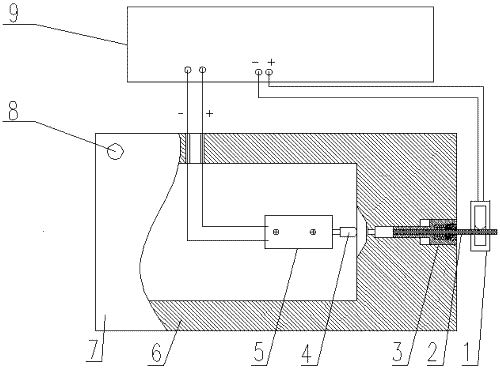
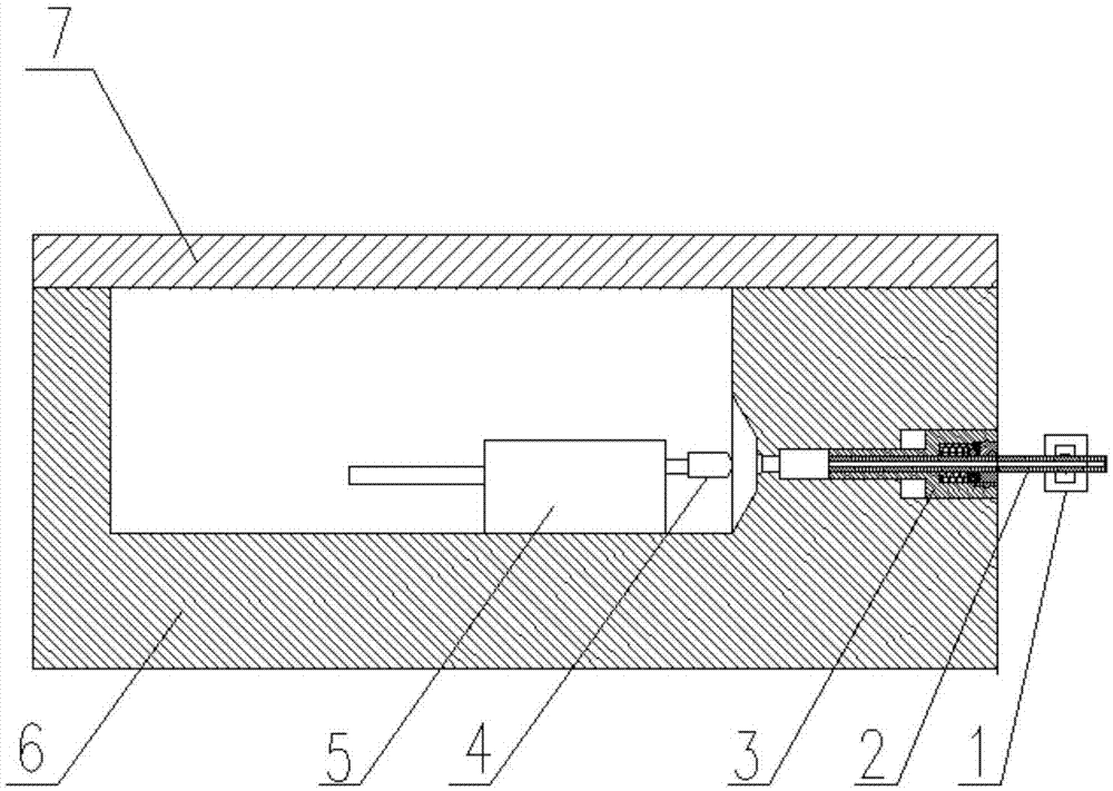
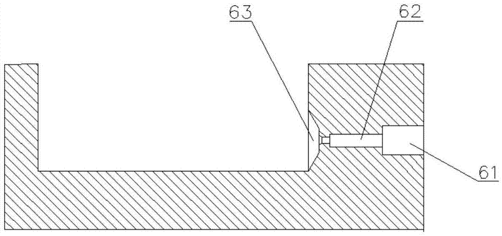
[0028] The technical solution of the present invention will be further described below in conjunction with the accompanying drawings, but the scope of protection is not limited to the above.

[0029] Such as figure 1 , figure 2 , image 3 , Figure 4 , Figure 5 A device for deferred body testing shown includes a base 6, a signal processor 9, a signal detector 1, a cover plate 7, a detonating tube 2, a quick connection device 3, and an operational amplifier 5, a signal detector 1 and an operational amplifier 5 are respectively connected to the signal processor 9, the signal detector 1 is installed on the detonating tube 2, the operational amplifier 5 is installed on the inner wall of the base 6, and the base 6 is a square cavity structure with an upper opening and a bottom sealed, the cover plate 7 is installed at the upper edge of the base 6. The side wall of the base 6 is sequentially provided with a connecting mounting hole 61, a filling chamber 62, and a photometric hole 63 ...


PUM


Abstract

The invention discloses a delay element test device and method. The device comprises a base, a signal processor, a signal detector, a cove plate, a detonating tube, a quick connecting device and an operational amplifier; the signal detector and the operational amplifier are connected with the signal processor; the signal detector is mounted on the detonating tube; the operational amplifier is mounted on the inner wall of the base; the base is of a square cavity structure with an opened upper end and a sealed bottom; the cover plate is mounted in the upper port of the base; a mounting hole, a filling chamber and a light measuring hole, communicated with each other, are formed in the side wall of the base in sequence from outside to inside; the detonating tube is mounted on the quick connecting device; the quick connecting device is mounted in the mounting hole; and a light measuring element is arranged in the light measuring hole, and is mounted on the operational amplifier. The delay element test device and method ignite a delay element through using the detonating tube, so that the delay element test safety is improved, the accident rate is reduced, and the production cost is reduced.

Description

Technical field [0001] The invention relates to the technical field of civilian blasting equipment production, in particular to a device and method for deferred body testing. Background technique [0002] The detonator delay body is assembled between the electric ignition element and the detonator, and is used to transmit the flame of the igniting powder head and then detonate the substance of the detonator. Testing the delay time of the delay body is an important technical theme in blasting engineering. Detonator lead wire extension body is used to measure the extension time of the extension body, most of which are used to cut the extension body into a small section in the extension body production line, and then install it on the detonator, detonate the detonator and collect relevant data, and test the delay body delay through calculation. Time, this kind of delayed body delay time test method requires the delayed body to be installed as a detonator. The whole process has certa...

Claims


Application Information

Patent Timeline
Patent Type & Authority Applications(China)
IPC IPC(8): F42C21/00
CPCF42C21/00
Inventor 刘国应聂煜李贞义黄明陈世雄陈辉峻赵郁欣冷德全
Owner GUIZHOU JIULIAN IND EXPLOSIVE MATERIALS DEV
Learn More