Light guide and illumination assembly incorporating the same

A technology of lighting components and lighting holes, which is applied in the field of light guides and can solve the problems of insufficient maximum luminosity and non-uniform luminosity.

Active Publication Date: 2016-03-30
BUHLER UK LTD
View PDF8 Cites 1 Cited by
  • Summary
  • Abstract
  • Description
  • Claims
  • Application Information

AI Technical Summary

Problems solved by technology

[0006] However, two specific disadvantages of these light guides are non-uniform luminosity over the viewable area and insufficient maximum luminosity to be compatible with all sorted commodities

Method used


Image

  • Light guide and illumination assembly incorporating the same
  • Light guide and illumination assembly incorporating the same
  • Light guide and illumination assembly incorporating the same

Examples


Embodiment Construction

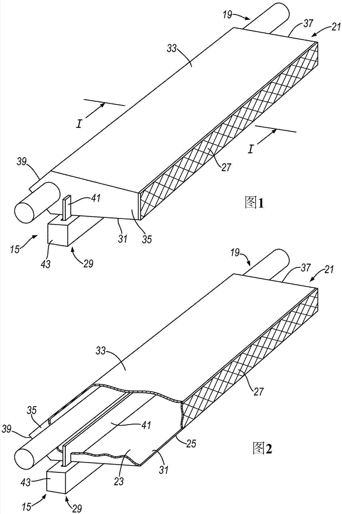
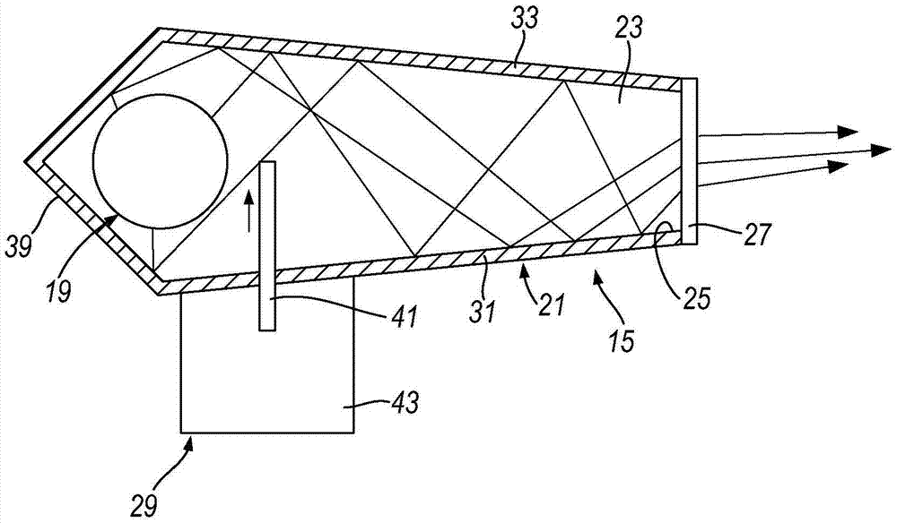
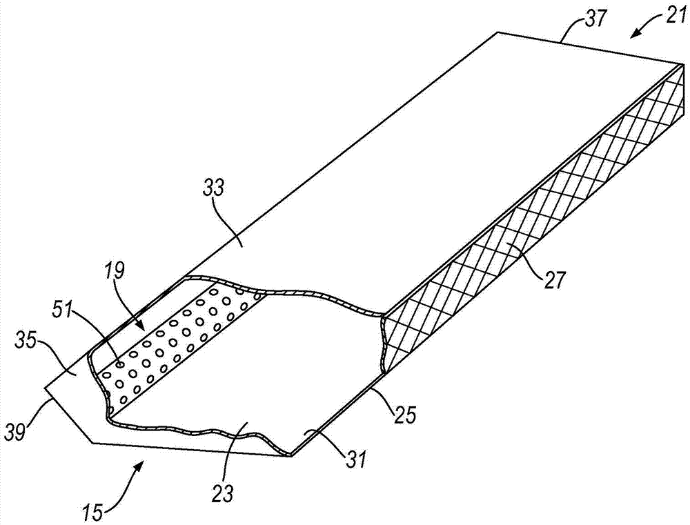
[0058] The lighting assembly comprises a light guide 15 and a light source 19 located within the light guide 15, in this embodiment at the back of the light guide.

[0059] The light guide 15 comprises a mirror box 21 defining a mirror cavity 23 containing a light source 19 therein, the cavity 23 comprising an illumination aperture 25, in this embodiment an elongated aperture, from which The illumination aperture produces the illumination; a light-transmitting diffuser 27 is located in the illumination aperture 25 to diffuse the illumination; and a shutter mechanism 29 shields the light source 19 and controls the luminous intensity of the illumination produced.

[0060] The mirror box 21 comprises: first and second main mirror parts 31, 33, in this embodiment elongated parts, the front edges of which define the illumination aperture 25; first and second end parts 35, 37 , which are located at each end of the main mirror parts 31, 33;

[0061] With this configuration, all light ...


PUM


Abstract

The invention provides a light guide (15) used for for delivering an illumination, in particular a reference or background illumination, the light guide comprising: a mirror box (21) which defines a mirror cavity (23), which receives a light source (19) therein, and includes an illumination aperture (25) from which illumination is delivered; a transmissive diffuser (27) which is located at the illumination aperture to render the illumination diffuse; and a shutter mechanism (41) which can be moved to the cavity to obstruct the light source and provide for control of the intensity of radiance of the delivered illumination. Thus, the control for the intensity of radiance of the delivered illumination can be determined by the position of the shutter in the cavity.

Description

[0001] This application is a divisional application of the Chinese invention patent application with application number 200980150631.9 and the title of the invention is "light guide and lighting assembly including light guide". technical field [0002] The present invention relates to a light guide for providing elongate illumination from a light source, in particular reference illumination (also often referred to as background illumination), and an illumination assembly comprising the light guide. Background technique [0003] The invention has a variety of uses, including providing reference illumination in sorting machines where a product such as food (eg, food) is imaged relative to a control reference or background. In such a sorter, the reference must have a physical extent that is large enough to fill the field of view of a single or multiple imaging cameras and yet accommodate positional errors due to manufacturing tolerances. The luminosity of the reference must be ...

Claims


Application Information

Patent Timeline
Patent Type & Authority Applications(China)
IPC IPC(8): G02B6/00G03B15/02G09F13/14G09F13/18
CPCG02B6/0055G02B6/0096G03B15/02G03B15/06G09F13/14G09F13/18G02B6/0018G02B6/0051F21V7/00F21V7/04G02B6/00G03B21/28F21V13/10
Inventor R·J·N·麦克莱恩
Owner BUHLER UK LTD
Why Eureka
Try Eureka