

Direct-current traction high-power power cable up to 1500V for rail transit
A technology of DC traction and power cables, applied in the direction of power cables with shielding layer/conductive layer, etc., can solve the problems of low transmission power and short service life, and achieve the effect of short service life and good signal transmission
Inactive Publication Date: 2016-03-30
WUXI YUDE CABLE TECH CO LTD
View PDF5 Cites 0 Cited by
- Summary
- Abstract
- Description
- Claims
- Application Information
AI Technical Summary
Problems solved by technology
Traditional power cables have low transmission power and short service life
Method used
View moreImage
Smart ImageViewing Examples

Examples
Embodiment 1
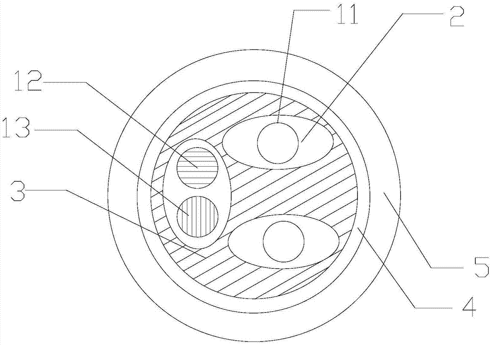
[0008] Such as figure 1 The present invention discloses a rail transit 1500V and below DC traction high-power power cable, which includes two single conductors 11 arranged in parallel in the horizontal direction and a double conductor arranged in the longitudinal direction, and the double conductor includes a tinned copper conductor 12 and A glass fiber-coated copper conductor 13, the single conductor 11 is a copper conductor, the single conductor 11 and the double conductor are covered with an inner shielding layer 2, and the inner shielding layer 2 is covered with an insulating layer 3 and an outer shielding layer 4 in turn and jacket5.
Login to View More PUM
 Abstract
The invention discloses a direct-current traction high-power power cable up to 1500V for rail transit. The direct-current traction high-power power cable comprises two single conductors and a double conductor, wherein the two single conductors are transversely arranged in parallel; the double conductor is longitudinally arranged, and comprises a tinned copper conductor and a glass fiber-coated copper conductor; each single conductor is a copper conductor; an inner shielding layer coats the outside of the single conductors and the double conductor; and an insulating layer, an outer shielding layer and an outer sheath sequentially coat the outside of the inner shielding layer. Compared with the prior art, the direct-current traction high-power power cable disclosed by the invention is better in signal transmission and shorter in service lifetime; and the single conductors and the double conductor can simultaneously work to compensate the mutual shortages.
Description
technical field [0001] The invention belongs to the field of cables, and in particular relates to a rail transit 1500V and below DC traction high-power power cable. Background technique [0002] The technical requirements of the existing rail transit 1500V and below DC traction power cables are implemented in GB / T28429-2012: Rail transit 1500V and below DC traction power cables and accessories are used for power transmission of rail transit DC traction systems, and their structure is from center to The outer layer is: cable copper conductor, extruded cross-linked polyethylene or ethylene propylene rubber or hard ethylene propylene rubber insulation layer. When necessary, there can be water blocking layer; when necessary, there can be waterproof layer; when necessary, there can be fire barrier layer; when necessary, there can be armor layer; coat. Traditional power cables have low transmission power and short service life. Contents of the invention [0003] Purpose of th...
Claims
Login to View More Application Information
Patent Timeline
 IPC IPC(8): H01B9/02
Inventor徐福荣王岩
OwnerWUXI YUDE CABLE TECH CO LTD