

Electrical connector
- Summary
- Abstract
- Description
- Claims
- Application Information
AI Technical Summary
Benefits of technology
Problems solved by technology
Method used
Image

Examples
first embodiment
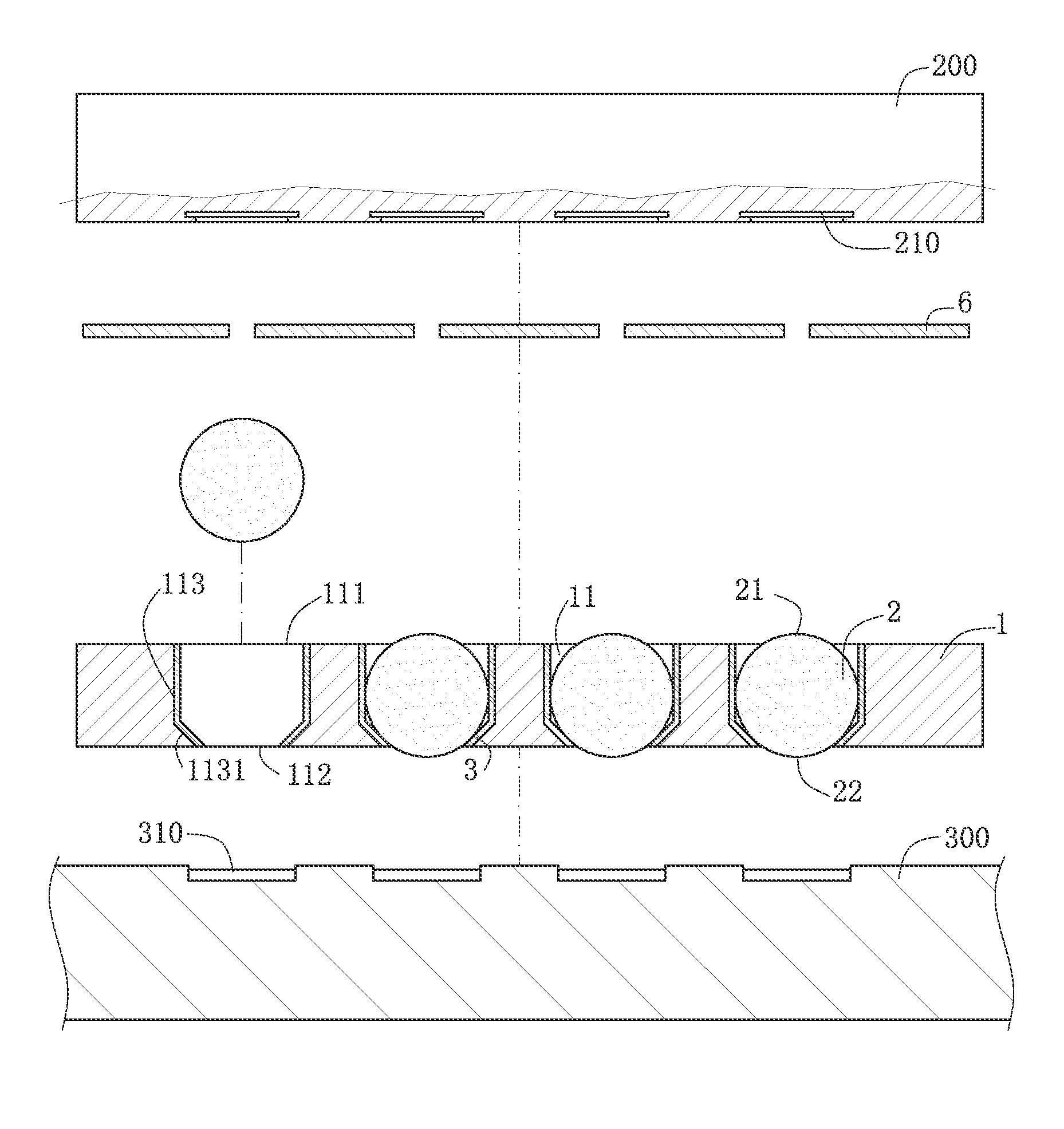
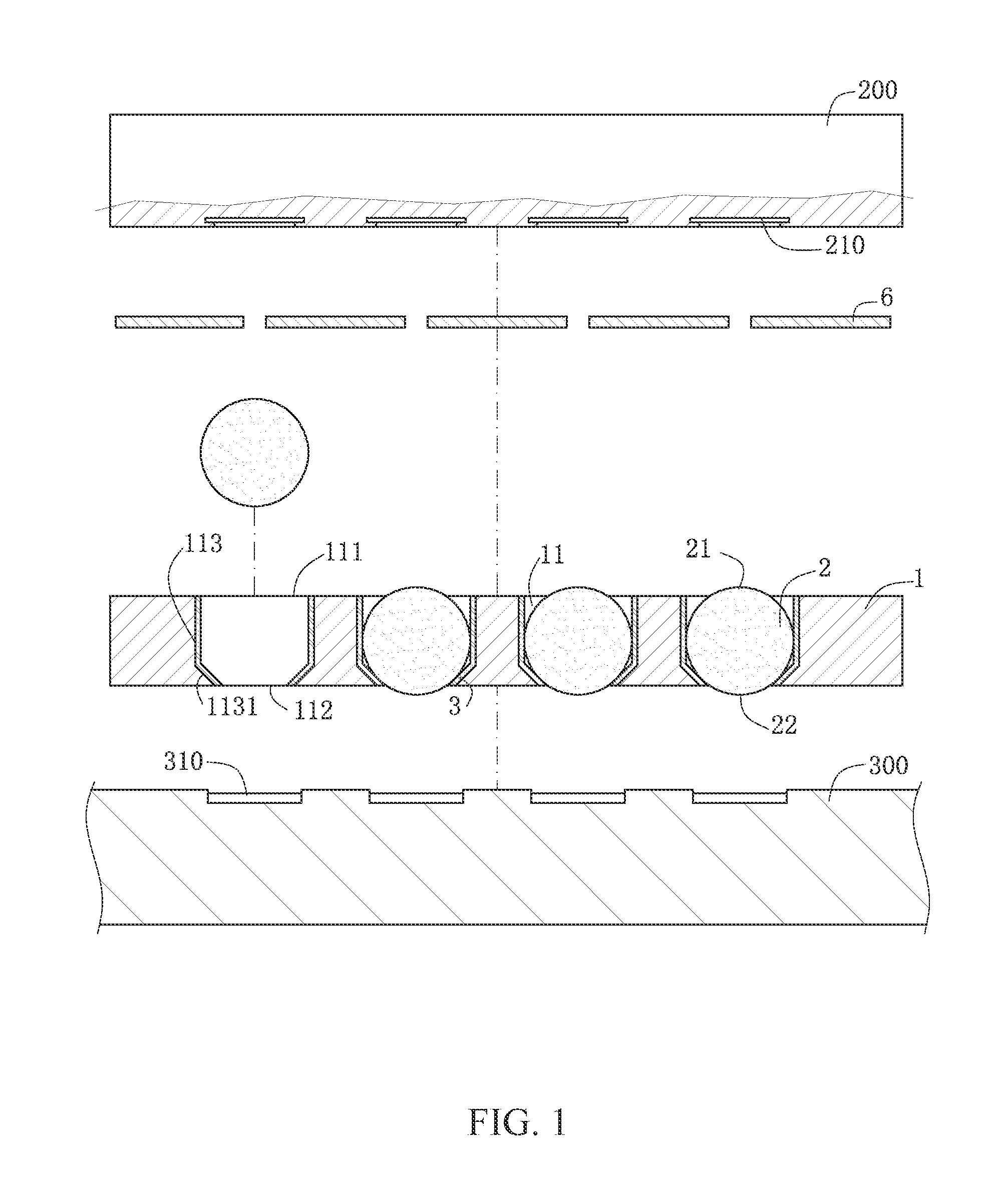
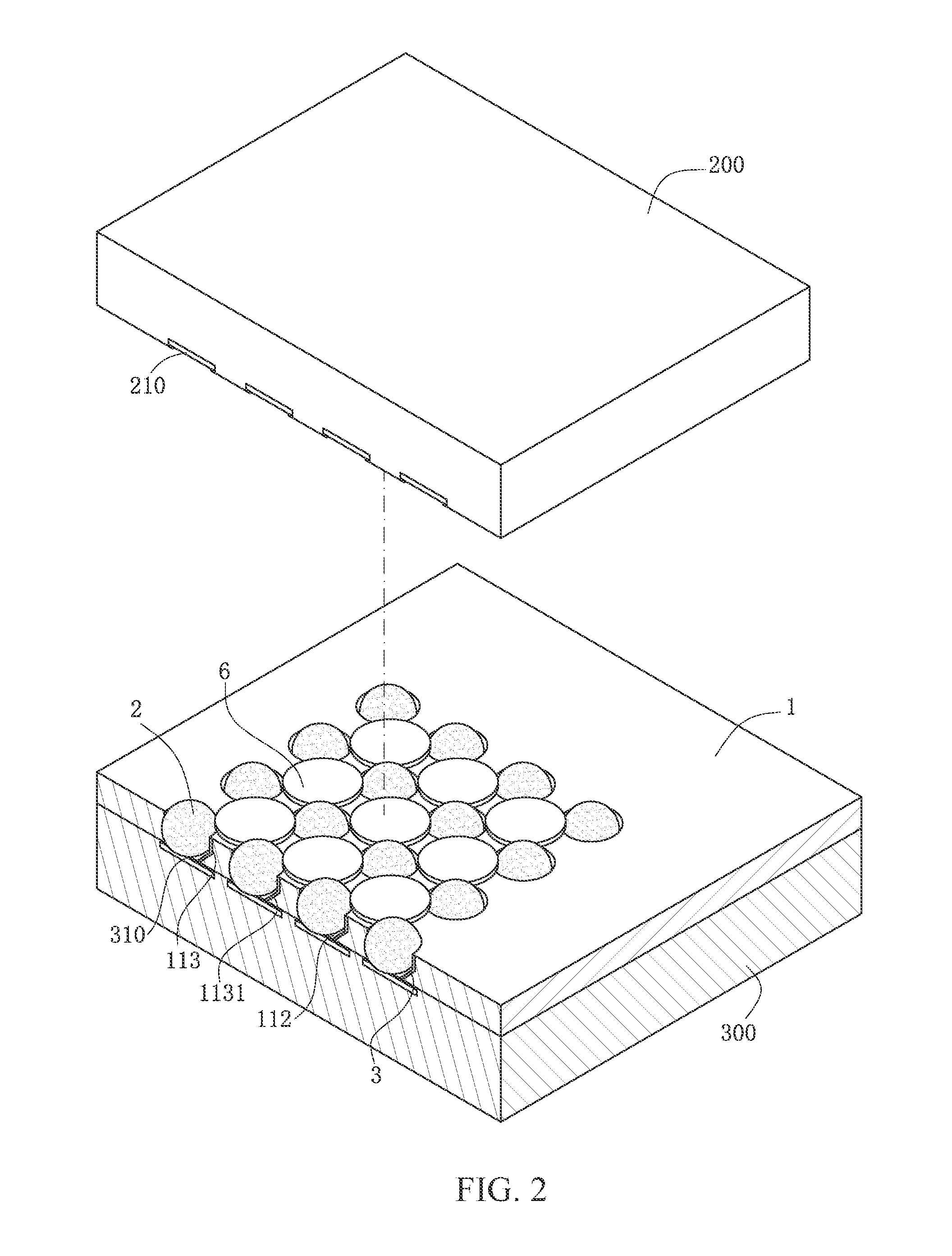
[0028]As shown in FIG. 1 to FIG. 3, as the present invention, an electrical connector is used for electrically connecting a first electronic element and a second electronic element. In this embodiment, the first electronic element is a chip module 200, and the second electronic element is a circuit board 300. The chip module 200 is provided with multiple first conducting portions 210, and the circuit board 300 is provided with multiple second conducting portions 310. The electrical connector includes an insulation body 1 and multiple first conductors 2. The first conductors 2 are accommodated in the insulation body 1 and electrically conduct the chip module 200 and the circuit board 300. In other embodiments, the first electronic element and the second electronic element may also be other components.
[0029]The insulation body 1 is a plate-shaped body, made of plastic which is not easily deformed. The insulation body 1 includes receiving holes 11 accommodating the first conductors 2. ...
third embodiment
[0034]As shown in FIG. 5, as the present invention, an electrical connector is used for electrically connecting a chip module 200 to a circuit board 300. The chip module 200 includes multiple first conducting portions 210, and the circuit board 300 includes multiple second conducting portions 310. The electrical connector includes an insulation body 1. The insulation body 1 is provided with multiple receiving holes 11 corresponding to the chip module 200 and the circuit board 300, and a first conductor 2 is accommodated in the receiving hole 11.
[0035]The electrical connector further includes an elastomer 5. The elastomer 5 is a sphere-shaped body or bulk-shaped body that is made of a foaming material. Gallium or gallium alloy is disposed on the elastomer 5. The elastomer 5 is disposed in the receiving hole 11. In this embodiment, the elastomer 5 is disposed between the first conductor 2 and the second conducting portion 310, and elastically urges the first conductor 2. The elastomer...
fifth embodiment
[0041]As shown in FIG. 7 to FIG. 9, as the present invention, an electrical connector is in a ball grid array (BGA) mode, and is used for electrically connecting a chip module 200 and a circuit board 300. The chip module 200 includes multiple first conducting portions 210. The first conducting portion 210 is a tin ball. The circuit board 300 includes multiple second conducting portions 310. The electrical connector includes an insulation body 1, multiple first conductors 2 and multiple liquid conductors 4. The first conductors 2 and the liquid conductors 4 are accommodated in the insulation body 1.
[0042]The insulation body 1 is a plate-shaped body that is made of plastic not easily deformed. The insulation body 1 is provided with receiving holes 11 accommodating the first conductors 2 and the liquid conductors 4. The receiving hole 11 runs through the insulation body 1, and is formed with a first opening 111 on an upper surface of the insulation body 1 and formed with a second openi...
PUM
 Abstract
Description
Claims
Application Information