Rotary shaft of permanent magnet motor and installation method thereof

A technology of permanent magnet motor and installation method, applied in the direction of electromechanical devices, manufacturing motor generators, electrical components, etc., can solve the problems of increasing the difficulty of magnetic bearing control, radial magnetic bearing interference, etc., to avoid thermal demagnetization, eliminate interference, The effect of improving the success rate

Active Publication Date: 2018-08-07
GREE ELECTRIC APPLIANCES INC +2
View PDF6 Cites 0 Cited by
  • Summary
  • Abstract
  • Description
  • Claims
  • Application Information

AI Technical Summary

Problems solved by technology

Although this high-speed rotating shaft structure has been treated with magnetic isolation baffles, its main shaft is generally made of magnetically conductive material, so the magnetic field generated by the ring magnet at the motor shaft will also pass through the main shaft and the bearing shafts on both sides. The coupling loop interferes with the magnetic field of the radial magnetic bearing and increases the difficulty of controlling the magnetic bearings on both sides

Method used


Image

  • Rotary shaft of permanent magnet motor and installation method thereof
  • Rotary shaft of permanent magnet motor and installation method thereof
  • Rotary shaft of permanent magnet motor and installation method thereof

Examples


Embodiment Construction

[0034] The present invention is described below based on examples, but the present invention is not limited to these examples. In the following detailed description of the invention, some specific details are set forth in detail. The present invention can be fully understood by those skilled in the art without the description of these detailed parts. To avoid obscuring the essence of the present invention, well-known methods, procedures, procedures, and components have not been described in detail.

[0035] The following defines the directions in this application as follows: the inner side is the side close to the axis of the rotating shaft in the radial direction, and the outer side is the side away from the axial direction of the rotating shaft; the end face is a surface located at one end in the axial direction and generally perpendicular to the axis of the rotating shaft .

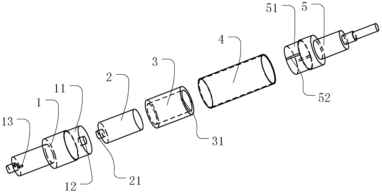
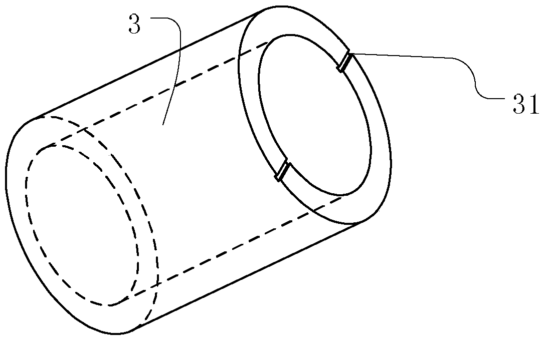
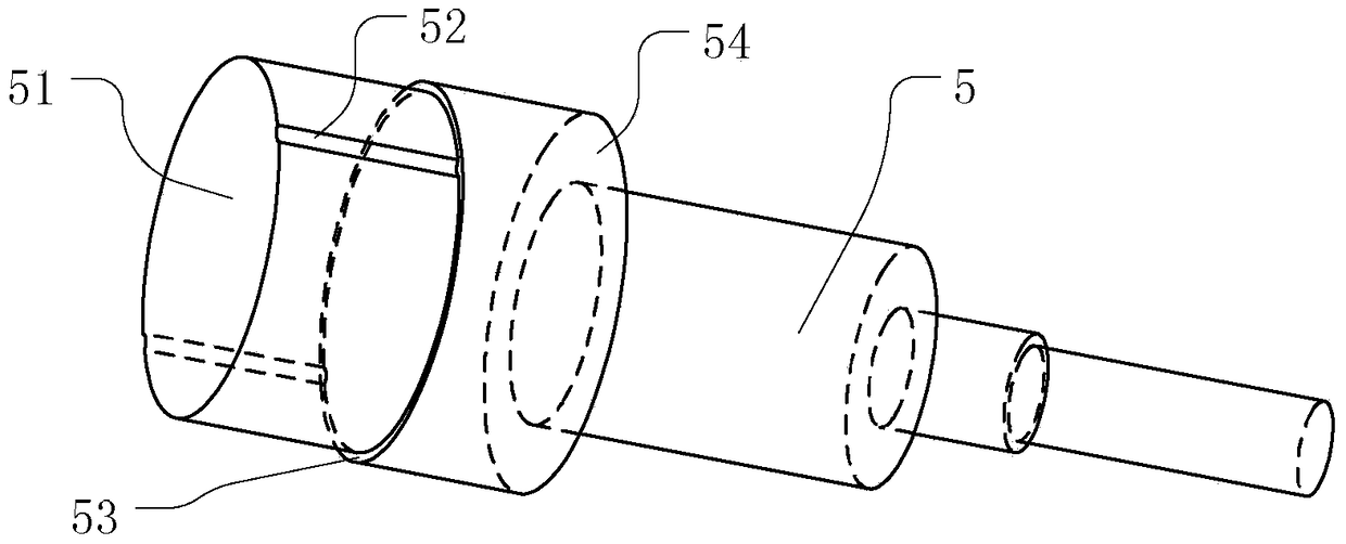
[0036] Such as Figure 1-5 As shown, the present application relates to a permanent magnet motor...


PUM


Abstract

The invention aims at providing a permanent magnet motor rotating shaft and a mounting method thereof, and aims at mainly solving the problem of a disturbed magnetic field generated by a main shaft of an existing permanent magnet motor rotating shaft. According to the technical scheme, the permanent magnet motor rotating shaft comprises a first rotating shaft end part, a second rotating shaft end part, magnetic steel and a magnetic conductive core; and the rotating shaft end parts are made of non-magnetic conductive materials. Through the arrangement, the axial flux leakage is greatly reduced.

Description

technical field [0001] The invention relates to the field of motors, in particular to a permanent magnet motor shaft and an installation method thereof. Background technique [0002] The traditional high-speed permanent magnet motor shaft structure, the high-speed permanent magnet motor shaft uses a whole ring magnet (surface-mounted magnet), the shaft has a main shaft through the ring magnet, and the magnet is protected by a sheath And to transmit torque, the two ends of the magnetic steel are also equipped with magnetic isolation baffles. Although this high-speed shaft structure has been treated with a magnetic isolation baffle, its main shaft is generally made of magnetically conductive material, so the magnetic field generated by the ring magnet at the motor shaft will also be formed by the main shaft and the bearing shafts on both sides. The coupling loop interferes with the magnetic field of the radial magnetic bearing and increases the difficulty of controlling the m...

Claims


Application Information

Patent Timeline
Patent Type & Authority Patents(China)
IPC IPC(8): H02K7/00H02K15/00
Inventor 刘健宁贾金信张芳龚高张小波钟成堡李广海郭长光田思园
Owner GREE ELECTRIC APPLIANCES INC
Why Eureka
Try Eureka