
Linear Rotary Drilling Motor

A straight line and stator technology, applied in electromechanical devices, electrical components, propulsion systems, etc., can solve problems affecting work efficiency and economic benefits, difficult drilling positions or depths, and low drilling accuracy, so as to improve the utilization of internal space , Improve the torque/thrust density, reduce the effect of axial magnetic flux leakage

Active Publication Date: 2022-05-10
ANHUI UNIV OF SCI & TECH
View PDF11 Cites 0 Cited by
  • Summary
  • Abstract
  • Description
  • Claims
  • Application Information

AI Technical Summary

Problems solved by technology

It is widely used in drilling projects such as mine mining, coal mine excavation, and roadway bolting. However, it is difficult to accurately control the drilling position or depth during drilling operations, resulting in low drilling accuracy, which seriously affects work efficiency and economy. Benefit is the main problem facing the research of drilling robot technology

Method used


Image

  • Linear Rotary Drilling Motor
  • Linear Rotary Drilling Motor
  • Linear Rotary Drilling Motor

Examples


Embodiment Construction

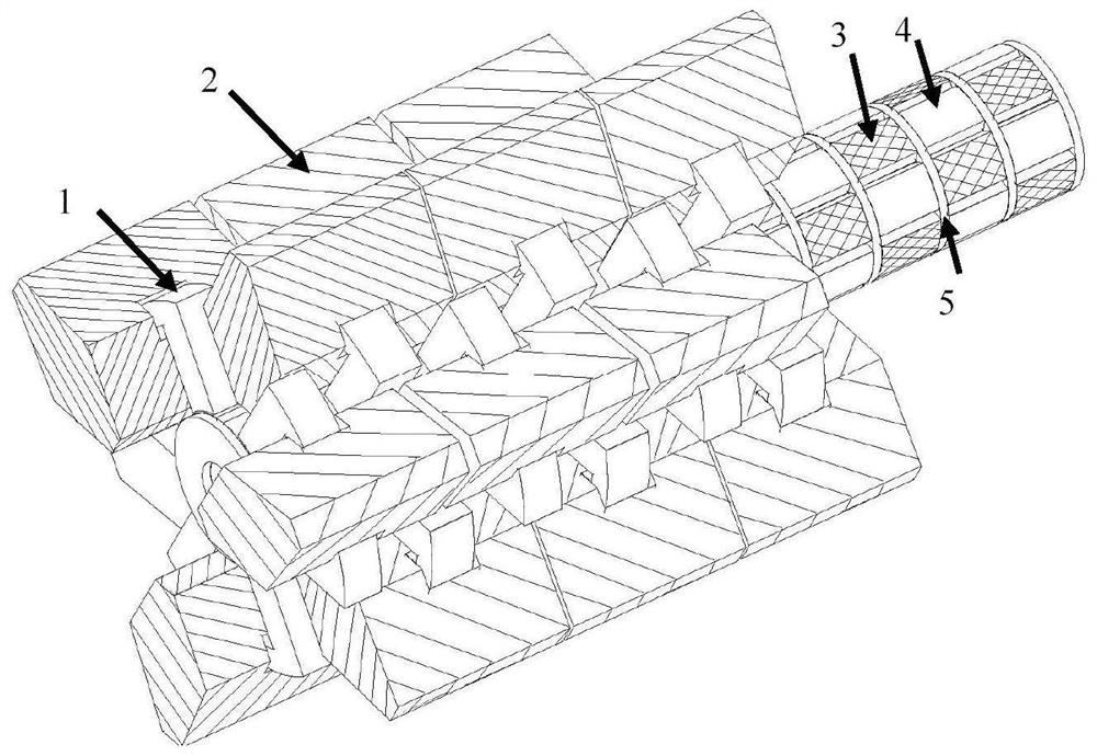
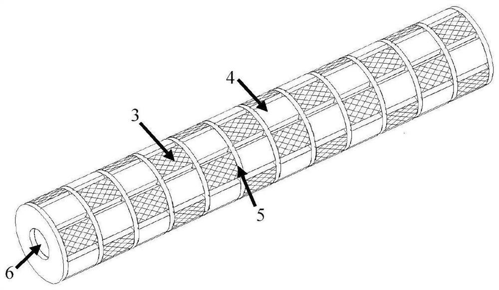
[0018] The linear rotary drilling motor, such as figure 1 As shown, the motor is composed of a U-shaped stator core (1), a ring winding (2), a permanent magnet S pole (3), a permanent magnet N pole (4) and a magnetic isolation ring (5). The mover structure is as follows image 3 As shown, it consists of a permanent magnet S pole (3), a permanent magnet N pole (4), a magnetic isolation ring (5) and a mover iron core (6).

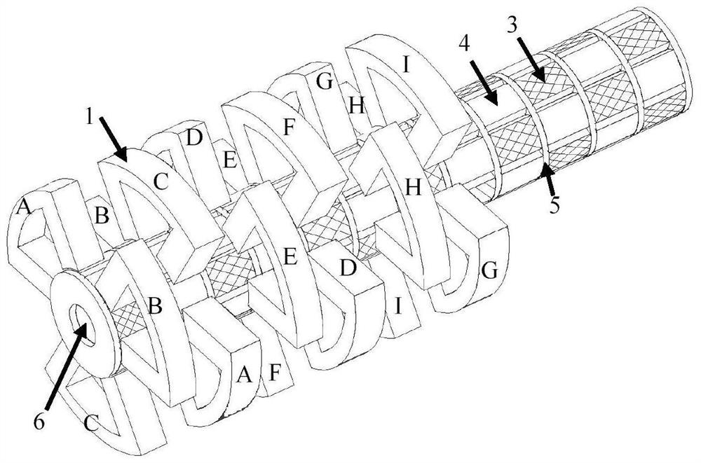
[0019] The stator part of the motor has three U-shaped stator cores in the circumferential direction, and the winding control form is (A, B, C) (D, E, F) (G, H, I) when rotating, and in the axial direction U Stator cores are arranged in a staggered manner, and the control form of the winding is (A,D,G)(B,E,H)(C,F,I) during linear motion. The winding arrangement is as follows: figure 2 shown in . The ring winding can be wound and installed before the module is assembled, which simplifies the manufacturing and assembly process and reduces the cost of the mot...


PUM


Abstract

In order to meet the needs of drilling robots for two-degree-of-freedom linear rotation, the present invention proposes a radial magnetic circuit linear rotary drilling motor based on a U-shaped stator structure. The motor is composed of a stator part and a mover part. The stator part It consists of a modular U-shaped stator (1) and a ring winding (2). The ring winding is nested in the stator yoke. The U-shaped stators are arranged staggered in the axial direction, which improves the space utilization of the motor. The mover part is composed of permanent magnet N Pole (3), permanent magnet S pole (4), spacer ring (5) and mover (6). The permanent magnet pole surface is attached to the surface of the mover and arranged alternately. The magnetic ring, the motor uses the same two-dimensional radial magnetic circuit to realize the two-degree-of-freedom motion of linear rotation. Two different working principles are applied to the same motor structure, and the rotational motion is realized based on the principle of electromagnetic induction. Based on the transverse magnetic The linear motion is realized by the general principle, and the motor has the characteristics of high torque / thrust density.

Description

technical field [0001] The invention relates to the field of permanent magnet motors, in particular to an electromagnetic device that can realize linear or rotational two-degree-of-freedom motion. Background technique [0002] Drilling robot is a typical intelligent and unmanned technical equipment, and it is one of the key technologies for the development of my country's intelligent manufacturing industry. It is widely used in drilling projects such as mine mining, coal mine excavation, and roadway bolting. However, it is difficult to accurately control the drilling position or depth during drilling operations, resulting in low drilling accuracy, which seriously affects work efficiency and economy. Efficiency is the main problem facing the research of drilling robot technology. The end drive mechanism of the mechanical arm of the drilling robot is directly connected with the two-degree-of-freedom linear rotary motor, which can not only improve the drilling speed and precis...

Claims


Application Information

Patent Timeline
Patent Type & Authority Patents(China)
IPC IPC(8): H02K1/12H02K1/278H02K41/02
CPCH02K1/12H02K1/278H02K41/02H02K2201/12
Inventor 郭凯凯
Owner ANHUI UNIV OF SCI & TECH
Learn More