
A forced-air cooling electronic chassis

A chassis and electronic technology, applied in the field of forced exhaust heat dissipation electronic chassis, can solve problems such as difficulty in exhausting hot air from the chassis, equipment heating, equipment failure reliability, etc., to improve ventilation effect, facilitate replacement, and avoid air short-circuit. Effect

Active Publication Date: 2017-09-12
THE 28TH RES INST OF CHINA ELECTRONICS TECH GROUP CORP
View PDF4 Cites 0 Cited by
  • Summary
  • Abstract
  • Description
  • Claims
  • Application Information

AI Technical Summary

Problems solved by technology

However, if the electronic chassis is installed inside a standard cabinet, and the equipment inside the cabinet is relatively compact, and there are equipment on the upper and lower sides of the electronic chassis, it is difficult to achieve the ideal heat dissipation effect by adopting the method of bottom air intake and top exhaust
The main reasons are: first, the bottom of the electronic case is close to the equipment below it, resulting in poor air flow, and it is difficult for cold air to enter the inside of the case; It will cause poor air flow, make it difficult for hot air to escape from the chassis, and the hot air exhausted from the top will cause the equipment above it to heat up, which may lead to equipment failure or reduced reliability

Method used


Image

  • A forced-air cooling electronic chassis
  • A forced-air cooling electronic chassis
  • A forced-air cooling electronic chassis

Examples


Embodiment Construction

[0019] The present invention will be described in detail below in conjunction with the accompanying drawings.

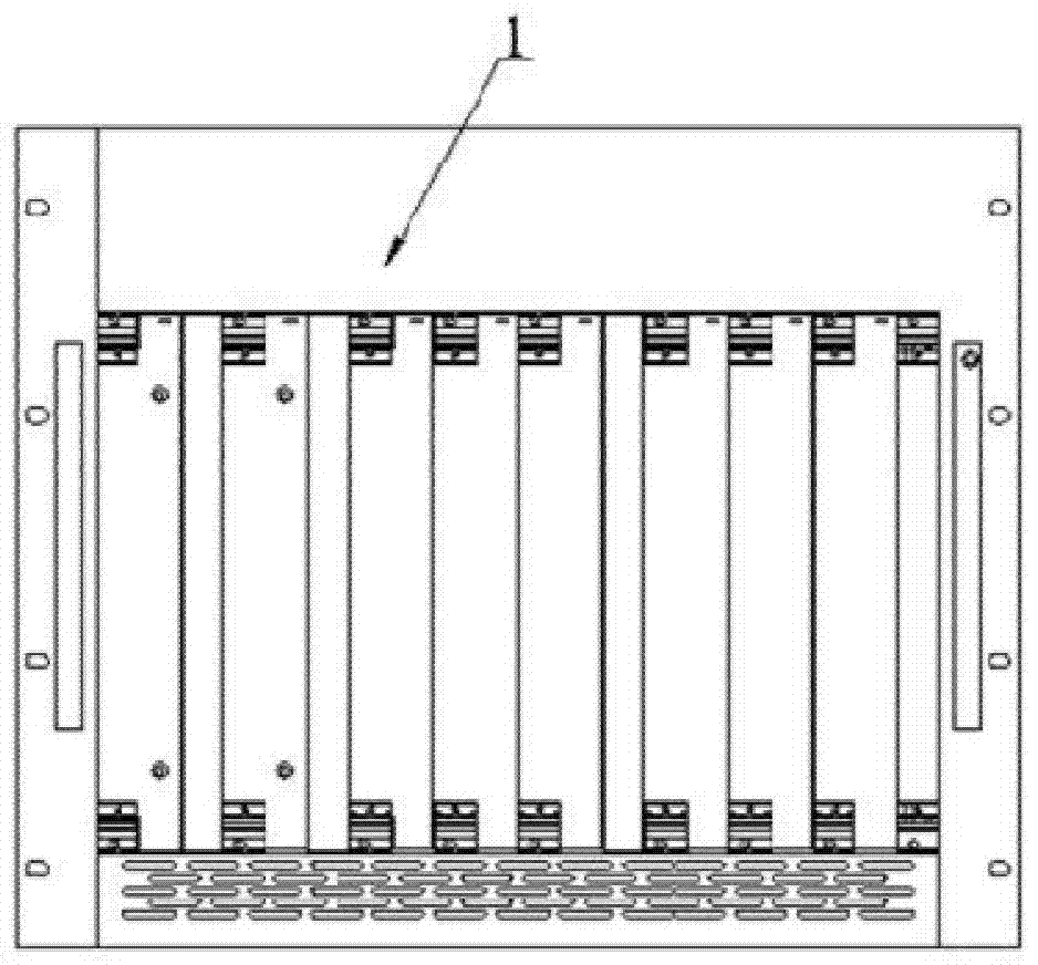
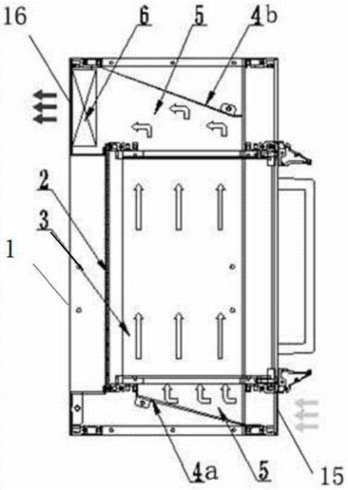
[0020] like figure 1 and figure 2 , is a schematic diagram of the composition of the system equipment and the air duct of the present invention, including a chassis body 1, a backplane 2, a plug-in board 3, a first air deflector 4a, a second air deflector 4b, an air duct 5, an exhaust fan 6, and an air inlet 15 And the air outlet 16, the backplane 2 and the plug-in board 3 are arranged in the case body 1, with the end of the air inlet of the case as the front part, the lower end of the front part of the case is provided with an air inlet 15, and the rear end of the air inlet 15 is provided with a first air guide plate 4a, the upper end of the rear part of the cabinet is provided with an air outlet 16, the rear end of the air outlet 16 is provided with a second air deflector 4b, and the air outlet 16 is also provided with an exhaust fan 6, and the electronic cabinet...


PUM


Abstract

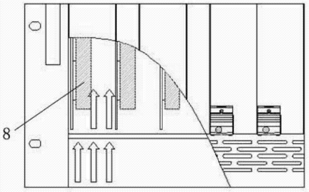
The invention discloses a forced air exhaust type radiating electronic case. The case comprises a case body and a package board arranged in the case body; the case body further comprises an air inlet formed in the lower part and an air outlet formed in the upper part; a first air deflector is arranged in the air inlet; the first air deflector extends from the bottom of the case body to the interior upward side of the case body in an inclined manner; a second air deflector is arranged in the air outlet; the second air deflector extends from the top of the case body to the interior downward side of the case body in an inclined manner; an exhaust fan is arranged in the air outlet; the air inlet, the first air deflector, the second air deflector, the air outlet and the exhaust fan enable an air channel in the case body to be a taper air channel; the package board is positioned in the taper air channel; the package board is provided with a radiator; a wind shield is arranged at the lower end of the radiator; and the wind shield is connected with the bottom of the case body through a wind shield rapid replacement mechanism.

Description

technical field [0001] The invention relates to a case, in particular to a forced-air cooling electronic case. Background technique [0002] Electronic chassis refers to an electronic equipment chassis that adopts standard buses such as CPCI and VPX or self-defined standard buses. It can insert plug-in boards of standard sizes with various functions. It is mainly composed of backplanes, plug-in boards, chassis and other components. Its characteristics It is the baffle that comes with the plug-in board, and the insertion direction is the bus backplane. The electronic chassis has the characteristics of standardization of plug-in board modules, convenient plugging and unplugging, and free expansion. It is widely used in servers and special computers. With the rapid development of informatization, the integration of plug-in boards is getting higher and higher, and the power of single boards is increasing, resulting in a very large heat generation in the entire electronic chassi...

Claims


Application Information

Patent Timeline
Patent Type & Authority Patents(China)
IPC IPC(8): H05K7/20
CPCH05K7/20145
Inventor 王连坡徐勇茅文深顾海峰刘永
Owner THE 28TH RES INST OF CHINA ELECTRONICS TECH GROUP CORP
Learn More