Linear bidirectional cutting platform

A cutting platform and linear technology, applied in metal sawing equipment, sawing machine, metal processing equipment, etc., can solve the problems of strong vibration, heavy chainsaw, and small size of small workpieces, so as to achieve stable operation and improve labor efficiency , the effect of saving manpower

Inactive Publication Date: 2016-04-06
TIANJIN HAICI TECH CO LTD
View PDF5 Cites 9 Cited by
  • Summary
  • Abstract
  • Description
  • Claims
  • Application Information

AI Technical Summary

Problems solved by technology

[0002] Most of the cutting in the prior art is done by using a saw blade. However, small workpieces are small in size. On the one hand, it is inconvenient for human hands to take them. On the other hand, they may accidentally injure human hands during cutting, which is not conducive to labor safety.
In addition, when cutting fixed objects in the prior art, the chainsaw is moved to cut. The mass of the chainsaw is relatively heavy, and the vibration is strong during movement. In addition, the movement of the chainsaw is also relatively dangerous.

Method used


Image

  • Linear bidirectional cutting platform
  • Linear bidirectional cutting platform
  • Linear bidirectional cutting platform

Examples


Embodiment Construction

[0029] It should be noted that, in the case of no conflict, the embodiments of the present invention and the features in the embodiments can be combined with each other.

[0030] The present invention will be described in detail below with reference to the accompanying drawings and examples.

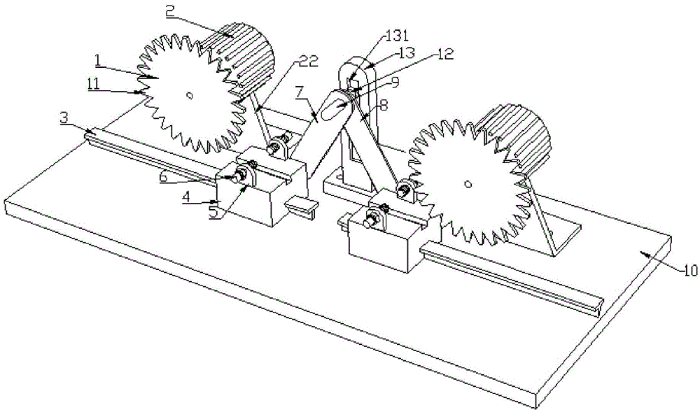
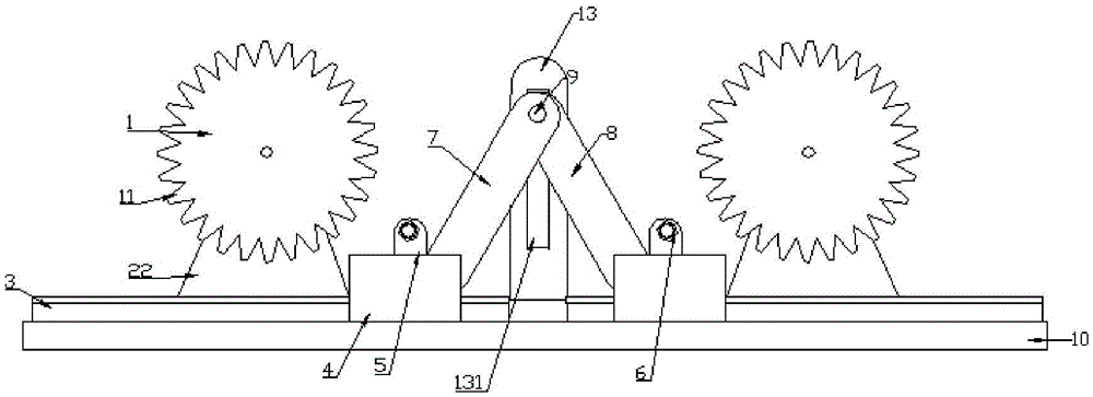
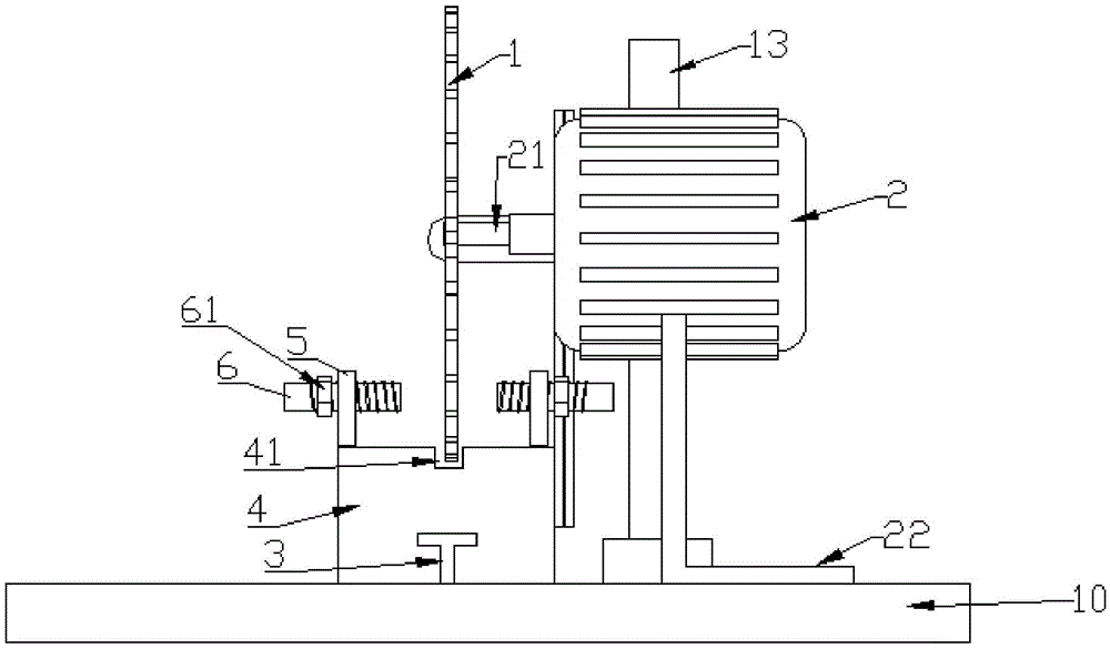
[0031] A linear two-way cutting platform, including flat, 10, above the platform 10 is provided with a connecting rod a7 and a connecting rod b8, the connecting rod a7 and the connecting rod b8 are hingedly connected, and the connecting rod b8 is fixedly connected to the limit mechanism 12. The end of the limiting mechanism 12 is provided with a limiting block 121, the limiting plate 13 is fixed on the platform 10, the bottom of the limiting plate 13 is provided with a screw hole c132, the limiting plate 13 is connected to the The platform 10 is fixedly connected by screws passing through the thread c132, and the limiting plate 13 is provided with a limiting groove 131 matching the shape...


PUM


Abstract

The invention provides a linear bidirectional cutting platform which comprises a platform body, a connecting rod a and a connecting rod b, wherein the connecting rod a and the connecting rod b are connected in a hinged mode. The connecting rod b is fixedly connected with a limiting mechanism. A limiting block is arranged at the end of the limiting mechanism. A limiting plate is fixed to the platform body. Screw holes c are formed in the bottom of the limiting plate. The limiting plate and the platform body are fixedly connected through screws penetrating through the screw holes c. A limiting groove is formed in the limiting plate. The limiting block is a cube. The limiting groove is a groove body. The left end of the connecting rod a is connected with a sliding block in a hinged mode. The right end of the connecting rod b is connected with a sliding block in a hinged mode. The sliding blocks are slidably connected with sliding rails. Sliding grooves matched with the sliding rails in shape and dimension are formed in the lower portions of the sliding blocks. Fastening seats are arranged on each sliding block. An electric saw groove is formed in the upper end face of each sliding block. Screw holes a are formed in the fastening seats. A threaded rod is sleeved with the corresponding screw hole a. Electric saw blades are arranged above the sliding rails. According to the linear bidirectional cutting platform, operation can be achieved by pushing a handle, labor is saved, the labor efficiency is improved through double stations, and the stability of the movement of the connecting rods can be guaranteed through the arrangement of the limiting mechanism.

Description

technical field [0001] The invention belongs to the field of workpiece cutting, in particular to a linear bidirectional cutting platform. Background technique [0002] Most of the cutting in the prior art is by using a saw blade to saw off, but the small workpiece is small in size, on the one hand it is inconvenient to take by hand, on the other hand it will accidentally injure the hand during cutting, which is not conducive to labor safety. In addition, to cut a fixed object in the prior art, the chainsaw is moved to cut, the mass of the chainsaw is relatively heavy, and the vibration is strong during movement. In addition, the movement of the chainsaw is also relatively dangerous. Contents of the invention [0003] In view of this, the present invention aims to propose a double-station small workpiece cutting mechanism to overcome the deficiencies of the prior art, realize the clamping and cutting of small workpieces, and the human hands do not need to touch the electric...

Claims


Application Information

Patent Timeline
Patent Type & Authority Applications(China)
IPC IPC(8): B23D45/02B23D45/10B23D47/04
CPCB23D45/105B23D45/02B23D47/042
Inventor 马广胜
Owner TIANJIN HAICI TECH CO LTD
Why Eureka
Try Eureka