Magnetic attracting positioning type rotary platform

A rotating platform and positioning technology, which is applied in the direction of workbench, large fixed members, metal processing machinery parts, etc., can solve the problems of expensive setup cost, complicated servo motor structure, and difficulty in achieving high-precision positioning

Inactive Publication Date: 2016-04-06
GMT GLOBAL
View PDF9 Cites 7 Cited by
  • Summary
  • Abstract
  • Description
  • Claims
  • Application Information

AI Technical Summary

Problems solved by technology

[0002] In the structural design of the existing rotary platform, most of the drive source is composed of a servo motor; this structure is still found in practical application experience, because the structure of the servo motor is relatively complicated, and the installation cost is much higher than other motors. This causes the problem that the manufacturing of the rotating platform does not meet the best industrial economic benefits
[0003] In addition, the rotary platform uses a servo motor as the structural form o...

Method used


Image

  • Magnetic attracting positioning type rotary platform
  • Magnetic attracting positioning type rotary platform
  • Magnetic attracting positioning type rotary platform

Examples


Embodiment Construction

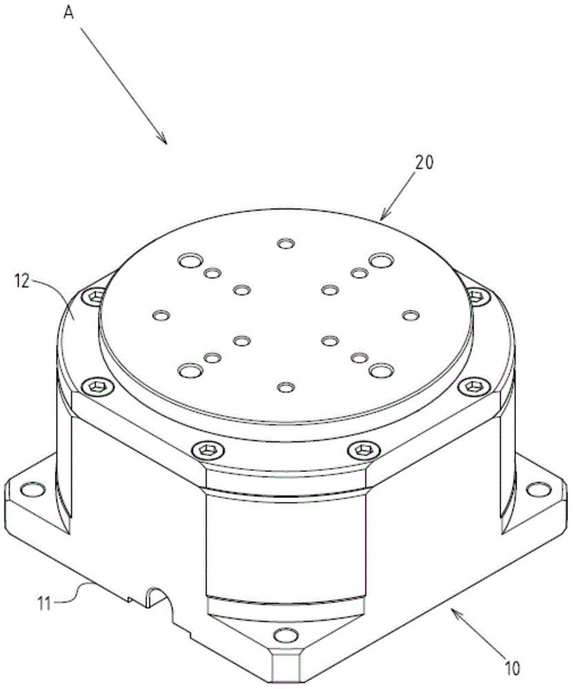
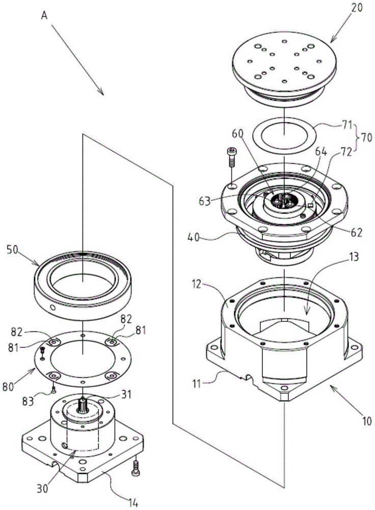
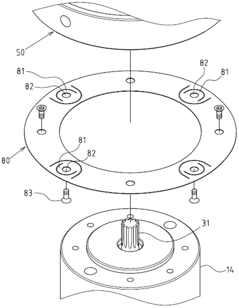
[0016] Such as figure 1 , 2 , 3, and 4 show preferred embodiments of the magnetic suction positioning rotary platform of the present invention, but these embodiments are only for illustration purposes, and are not limited by this structure in patent applications; the magnetic suction positioning type The rotating platform A includes the following components: a base 10, which is in the shape of a hollow seat, and includes a placement portion 11, a top 12, and a hollow accommodation portion 13, and the bottom end of the hollow accommodation portion 13 has a mounting seat 14 ; a rotating disk 20, which is pivotally assembled on the top 12 of the base 10 through a bearing 21, and is in a horizontally rotatable state; Inside the seat 14, a driving shaft 31 protrudes upward toward the center of the bottom of the rotating disk 20 at the top of the actuating device 30; And protrude downwards into the hollow housing portion 13 of the base 10, and be located at the peripheral interval...


PUM


Abstract

The invention discloses a magnetic attracting positioning type rotary platform. The magnetic attracting positioning type rotary platform comprises a base, a rotary disc, an actuating device, a magnetic conduction positioning part, an electronic control magnetic attracting part and a speed change mechanism, wherein the base comprises a containing part, a top and a hollow containing part, and an installation seat is arranged at the bottom end of the hollow containing part. The rotary disc is assembled at the top of the base in a pivoted mode. The actuating device is arranged in the installation seat of the base, and a driving shaft rod is arranged at the top end of the actuating device. The magnetic conduction positioning part is arranged at the bottom of the rotary disc, extends into the hollow containing part of the base in a protruding mode and moves together with the rotary disc. The electronic control magnetic attracting part is assembled and positioned on the installation seat of the base, corresponds to the position below the magnetic conduction positioning part, and can be powered on to generate magnetism so that the magnetic conduction positioning part and the rotary disc can be attracted and positioned. The speed change mechanism is arranged between the top end of the actuating device and the bottom of the rotary disc. In this way, the magnetic attracting positioning type rotary platform achieves the function of high-strength positioning.

Description

technical field [0001] The invention relates to a rotating platform; in particular, it refers to an innovative structural form of a magnetically positioned rotating platform. Background technique [0002] In the structural design of the existing rotary platform, most of the drive source is composed of a servo motor; this structure is still found in practical application experience, because the structure of the servo motor is relatively complicated, and the installation cost is much higher than other motors. This causes the problem that the manufacture of the rotating platform does not meet the best industrial economic benefits. [0003] In addition, the rotary platform uses a servo motor as the structural form of the rotary platform drive source. Since the rotary table of the rotary platform has a relatively large gravity, it will generate relatively large inertia after rotation, which makes it difficult for the rotary table to stop accurately when it stops. There are probl...

Claims


Application Information

Patent Timeline
IPC IPC(8): B25H1/02B23Q1/25
Inventor 庄运清陈柏嘉
Owner GMT GLOBAL
Why Eureka
Try Eureka