Perforating machine for plastic

A punching machine and plastic technology, applied in metal processing, etc., can solve the problems of plastic plate moving back and forth, increasing processing costs, wasting materials, etc., to achieve the effects of reducing processing costs, improving stability, and saving materials

Inactive Publication Date: 2016-04-06
CHONGQING RUITING PLASTIC
View PDF0 Cites 2 Cited by
  • Summary
  • Abstract
  • Description
  • Claims
  • Application Information

AI Technical Summary

Problems solved by technology

[0004] The punching machine in the prior art generally includes a punching rod arranged vertically. Two splints are arranged below the punching rod. The downward movement punches holes on the plastic sheet; during the punching process, since the two splints only clamp the plastic sheet in the left and right directions, when the punching rod acts on the plastic sheet, the plastic sheet tends to move back and forth , causing the tip of the punching rod to scratch the surface of the plastic sheet, and the scratches on the plastic sheet will be difficult to repair, which not only wastes materials, but also increases the processing cost

Method used


Image

  • Perforating machine for plastic

Examples


Embodiment Construction

[0014] The present invention will be described in further detail below by means of specific embodiments:

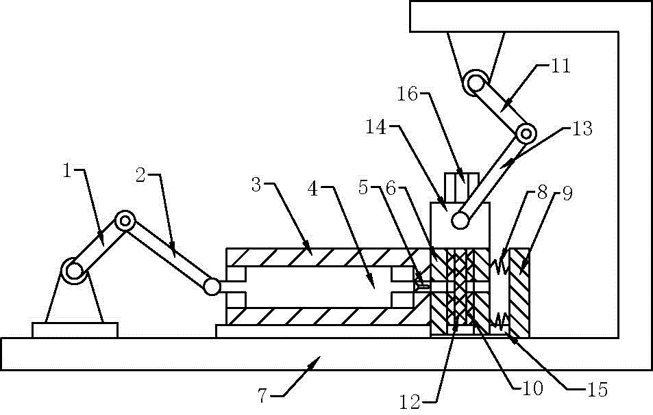
[0015] The reference signs in the drawings of the description include: the first crank 1, the first connecting rod 2, the chute 3, the punching rod 4, the tip 5, the splint 6, the frame 7, the compression spring 8, the fixed block 9, the rubber plate 10. The second crank 11, the plastic plate 12, the second connecting rod 13, the top pressure block 14, the first slide rail 15, and the second slide rail 16.

[0016] Example basic reference figure 1 Shown: a punching machine for plastic, including a frame 7, a punching rod 4, a chute 3 and two splints 6, the chute 3 is welded on the frame 7, and the punching rod 4 is slidably connected to the chute 3 Inside, the left end of the horizontal punching rod 4 is hinged with the first connecting rod 2, and the first connecting rod 2 is hinged with the first crank 1, and the first crank 1 is hinged on the first base welded on the ...


PUM


Abstract

The invention relates to a perforating machine for plastic. The perforating machine comprises a perforating rod, a sliding groove and two clamping plates. The perforating rod is connected into the sliding groove in a sliding mode, a first connecting rod is hinged to the left end of the perforating rod, and a first crank is hinged to the first connecting rod. A first slide rail is arranged at the right side of the perforating rod, the two clamping plates are sequentially connected to the first slide rail in a sliding mode from left to right, a fixing block is arranged at the right end of the first slide rail, and springs are connected between the clamping plate located on the side away from the sliding groove and the fixing block. The two clamping plates abut against each other, and an opening for the perforating rod to pass through is formed in the clamping plate located on the side close to the sliding groove. A second slide rail is arranged above the two clamping plates and connected with a pressing block in a sliding mode, a second connecting rod is hinged to the pressing block, and a second crank is hinged to the second connecting rod. Compared with the prior art, the pressing block and the two clamping plates are matched to enable a wood board to be fixed more stably, and therefore the stability of the wood board is enhanced, and the probability that the pointed end of the perforating rod makes scratches on the surface of the wood board is lowered.

Description

technical field [0001] The invention relates to a punching device, in particular to a punching machine for plastic. Background technique [0002] Ornaments are items used for decoration. The general purpose is to beautify personal instruments, decorate living rooms, beautify public environments, and decorate cars. Therefore, ornaments can be divided into the following categories: home accessories, clothing accessories, car accessories, etc. According to different materials, jewelry Can be divided into metal, jade, ceramics, crystal, glass, wood, plastic and so on. With the increasing number of people wearing jewelry, the wholesale jewelry industry is gradually rising. Because plastic jewelry is easier to process, light in weight and durable, it can not only be decorated by people, but also convenient for people to carry, so plastic jewelry is becoming more and more Be loved by people. [0003] Based on the above benefits of plastic jewelry, more and more suppliers have joi...

Claims


Application Information

Patent Timeline
Patent Type & Authority Applications(China)
IPC IPC(8): B26F1/02B26D7/02
CPCB26F1/02B26D7/025
Inventor 毛德中
Owner CHONGQING RUITING PLASTIC
Why Eureka
Try Eureka