Volute spiral spring type swing device with gap removing function

A scroll spring and oscillator technology, applied in the field of oscillators, can solve problems such as shaking of the swinging head, failure to meet the requirements, and affecting the repair effect of the water wall by the automatic welding robot, so as to avoid shaking of the swinging head and improve The effect of the repair effect

Inactive Publication Date: 2016-04-06
HARBIN KENENG CLADDING TECH
View PDF3 Cites 1 Cited by
  • Summary
  • Abstract
  • Description
  • Claims
  • Application Information

AI Technical Summary

Problems solved by technology

[0003] The present invention is to solve the problem that the oscillator body of the oscillator on the existing fully automatic welding robot adopts a worm gear reducer. After the oscillator body works for a long time, there will be a gap between the meshing teeth of the worm wheel and the worm during the transmission process. As a result, the swing head shakes, so that the swing does not reach the required angle, which affects the effect of the automatic cladding robot on the repair of the water wall. A scroll spring swinger with anti-backlash function is provided.

Method used


Image

  • Volute spiral spring type swing device with gap removing function
  • Volute spiral spring type swing device with gap removing function
  • Volute spiral spring type swing device with gap removing function

Examples


specific Embodiment approach 1

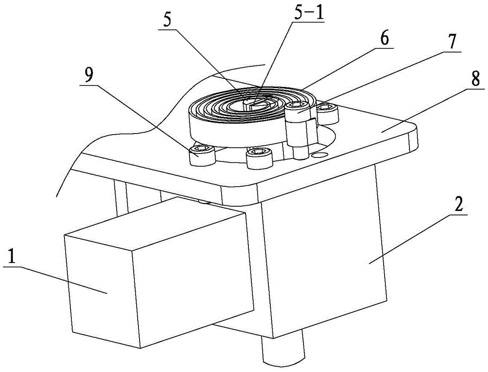
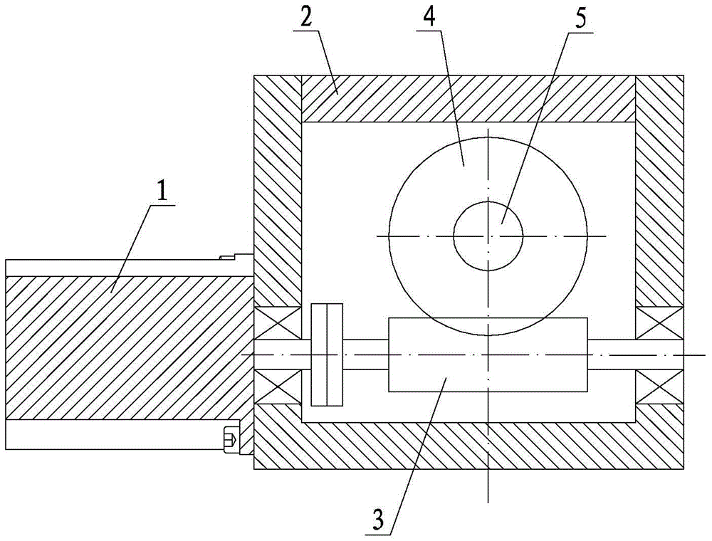
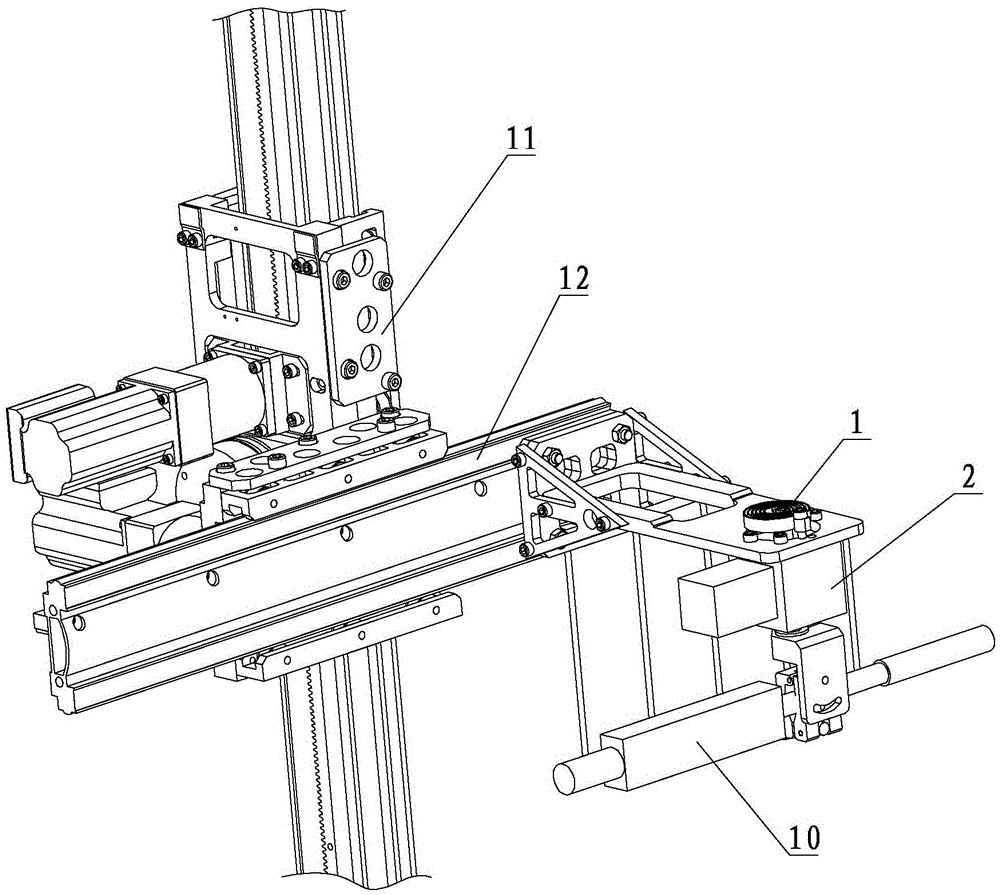
[0010] Specific implementation mode one: combine Figure 1 ~ Figure 3 Describe this embodiment, this embodiment comprises motor 1, casing 2, worm 3, worm wheel 4, driven shaft 5, scroll spring 6, screw 7 and fixing plate 8, and motor 1 is fixedly installed outside casing 2, and worm 3 is set in the housing 2 and connected with the output shaft of the motor through a coupling, the worm wheel 4 is engaged with the worm 3, the worm wheel 4 is fixed on the driven shaft 5, and the upper end of the driven shaft 5 is provided with a gap 5- 1. The scroll spring 1 is set outside the casing 2 and wound on the driven shaft 5. The inner end of the scroll spring 6 is inserted into the gap 5-1, and the outer end of the scroll spring 6 is fixed on the screw 7. , the screw 7 is threadedly connected with the fixed plate 8, and the housing 2 is fixed on the fixed plate 8. The fixed plate 8 is fixed on the transverse guide rail 12 .

specific Embodiment approach 2

[0011] Specific implementation mode two: combination image 3 Describe this embodiment, the difference between this embodiment and specific embodiment one is that it also has at least three positioning rods 9, at least three positioning rods 9 are evenly distributed along the outer surface of the scroll spring 6, and the lower ends of the positioning rods 9 It is threadedly connected with the fixed plate 8. Other components and connections are the same as those in the first embodiment.

[0012] Working principle: Before installing the welding gun, pre-tighten the scroll spring 6; the motor 1 drives the worm 3 to rotate, the worm 3 drives the worm wheel 4 to rotate, and the worm wheel 4 drives the driven shaft 5 to rotate. Under the action of the scroll spring 6, The teeth on the worm wheel 4 and the teeth on the worm 3 are made to be in close contact with each other, thereby compensating the gap generated between the worm wheel 4 and the worm 3 during transmission.


PUM


Abstract

The invention discloses a volute spiral spring type swing device with a gap removing function. The volute spiral spring type swing device aims to solve the problems that a worm gear reducer is adopted for a swing device on an existing full-automatic cladding robot, after the swing device works for a long time, gaps may be generated between engaged teeth in the transmission process of a worm gear and a worm, consequently, a swing head wobbles, swinging cannot reach the required angle, and the repairing effect of the full-automatic cladding robot on a water wall is influenced. A motor is fixedly arranged outside a shell; a worm is arranged in the shell and is connected with the output shaft of the motor through a coupler; a worm gear is engaged with the worm and is fixedly arranged on a driven shaft; a gap exists in the upper end of the driven shaft along the axis; a volute spiral spring is arranged outside the shell and is wound on the driven shaft; the inner end of the volute spiral spring is inserted in the gap; the outer end of the volute spiral spring is fixed to a screw; the screw is in threaded connection with a fixing plate; and the shell is fixedly arranged on the fixing plate. The volute spiral spring type swing device is used for the full-automatic cladding robot.

Description

technical field [0001] The invention relates to an oscillating device, in particular to a scroll spring type oscillating device with the function of eliminating backlash. Background technique [0002] The water wall is the main pressure-bearing part of the circulating fluidized bed boiler, mainly used to absorb the radiant heat of the boiler. During the operation of the circulating fluidized bed boiler, the flow direction of the solid material flowing down the inner wall of the furnace changes in the junction area, so The surface of the water-cooled wall is scoured. After a long period of scouring, the wall of the water-cooled wall is worn and thinned, and the strength is reduced. In addition, in the transitional area, because the solid material flowing down the wall is opposite to the solid material moving upward in the furnace, a vortex is locally generated. The swirling flow causes abrasion to the water cooling wall and shortens the service life of the water cooling wall....

Claims


Application Information

Patent Timeline
Patent Type & Authority Applications(China)
IPC IPC(8): C23C24/10
CPCC23C24/10
Inventor 马洪文王俊明王坤杨晓东严勤朱丽华展乾赵国权
Owner HARBIN KENENG CLADDING TECH
Why Eureka
Try Eureka