Filling device used for constant-temperature and constant-pressure continuous chemical charging of micro combined solid pushing engine

A constant temperature and constant pressure filling device technology, which is applied in the direction of rocket engine devices, jet propulsion devices, machines/engines, etc., can solve the problems of high risk, difficulty in controlling the amount of charge, and time-consuming rework, etc., and achieve low cost. Effect

Active Publication Date: 2016-04-06
HUBEI INST OF AEROSPACE CHEMOTECHNOLOGY
View PDF10 Cites 10 Cited by
  • Summary
  • Abstract
  • Description
  • Claims
  • Application Information

AI Technical Summary

Problems solved by technology

If the charge method of vacuum pouring is adopted, there are problems such as difficulty in tooling design, difficulty in controlling the amount of charge, frequent disassembly of tooling and high difficulty in cleaning.
However, the manual filling method has the disadvantages of frequent shoveling, high viscosity slurry, slow charging speed, and time-consuming rework.
[0004] To sum up, due to the characteristics of the micro-composite fixed propulsion engine, such as small structural size, small amount of charge and high risk, it is difficult to complete the charge pouring in a safe, large-scale and low-cost way by vacuum pouring and manual filling. craft

Method used


Image

  • Filling device used for constant-temperature and constant-pressure continuous chemical charging of micro combined solid pushing engine
  • Filling device used for constant-temperature and constant-pressure continuous chemical charging of micro combined solid pushing engine
  • Filling device used for constant-temperature and constant-pressure continuous chemical charging of micro combined solid pushing engine

Examples


Embodiment Construction

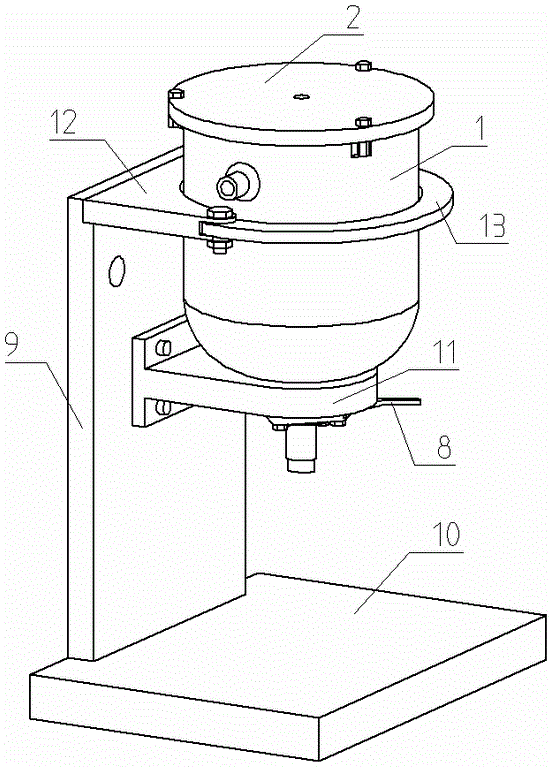
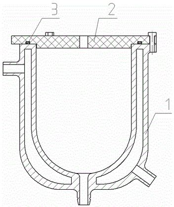
[0026] figure 1 , 2 Among them, the present invention includes a hopper mechanism that can realize sealing and constant temperature and pressure, a rubber hose valve mechanism for safe diversion and throttling, and an E-shaped support frame mechanism for connecting and fixing the hopper mechanism and the rubber hose valve mechanism. The hopper 1 of the hopper mechanism is a welded cavity wall structure (jacket structure). The upper end of the cavity wall hopper 1 is equipped with a transparent plexiglass cover plate 2, and the center of the cover plate 2 has a threaded hole communicating with the inner cavity of the hopper. , The port of the hopper 1 is connected with the cover plate 2 by bolts, and the sealing ring 3 is embedded in the annular groove of the cover plate 2 to realize sealing. The quick-plug connector connected to the threaded hole of the cover plate 2 is connected to the inlet pipe leading to nitrogen, so that the high-viscosity slurry in the hopper 1 can be p...


PUM


Abstract

The invention discloses a filling device used for constant-temperature and constant-pressure continuous chemical charging of a micro combined solid pushing engine. A cavity wall hopper is installed on a supporting rack. A cover plate is installed at the upper end of the cavity wall hopper. A venting port communicated with an inner cavity of the hopper is formed in the cover plate. A water inlet and a water outlet which are communicated with the cavity wall are formed in the side wall of the hopper. Circulating water is introduced into the cavity wall, so that the temperature of chemical paste in the hopper is constant. A discharging port communicated with the inner cavity of the hopper is formed in the bottom of the hopper. A throttling valve is installed at the dischargingport. The circulating water is introduced into the cavity wall of the hopper so that the temperature of the chemical paste in the hopper can be constant. After the cover plate and the hopper are sealed, nitrogen is introduced, and then the chemical paste filling speed can be controlled by controlling the air pressure. The valve can be opened and closed simply and safely by operating the throttling valve. The filling device is low in cost, convenient to mount, dismount and clean, and capable of achieving efficient safety production of a large scale of micro combined solid pushing engines.

Description

technical field [0001] The invention relates to a constant temperature and constant pressure precise filling device for high-viscosity fluid, which belongs to the technical field of fluid filling, and in particular to a filling device for batch production of micro-composite solid thrust motors. Background technique [0002] The compound fixed propulsion engine is one of the most important power devices in my country's national defense and aerospace industries, and its fuel is solid propellant. As an airborne carrier, the composite fixed propulsion engine needs extremely precise power parameters, and has extremely high requirements for the combustion stability and consistency of its internal propellant. Due to the diversity of the structural dimensions of the composite solid propulsion engine shell and the solid propellant formulation, different charging methods are required for engines with different structural functions. At present, the most common charging method of compo...

Claims


Application Information

Patent Timeline
Patent Type & Authority Applications(China)
IPC IPC(8): F02K9/24
Inventor 罗斌刘领张波魏明朱文博李月常
Owner HUBEI INST OF AEROSPACE CHEMOTECHNOLOGY
Why Eureka
Try Eureka