Novel inflating structure for airbag inflator

A buffer air bag and inflatable structure technology, applied in mechanical equipment, container manufacturing machinery, container filling methods, etc., can solve problems such as affecting the inflation efficiency, air leakage of the air cushion film, affecting the cushioning effect of the air cushion film, etc. Buffering effect, effect of preventing gas leakage

Active Publication Date: 2016-04-06
HANGZHOU BINGJIA TECH
View PDF6 Cites 6 Cited by
  • Summary
  • Abstract
  • Description
  • Claims
  • Application Information

AI Technical Summary

Problems solved by technology

[0002] When the existing cushion air bag inflator (such as ZL201420412981.6) inflates the air cushion film, it first cuts the inflated air cushion film, and then presses and heat seals it. , part of the gas in the air cushion film will leak, and the pressure of the gas in the air cushion cannot be guaranteed, which will affect the cushioning effect of the air cushion film during the use of the air cushion
[0003] At the same time, when the existing cushion air bag inflator (such as ZL201420412981.6) inflates the air cushion film, the gas will run forward along the inflation channel connected between the two air cushion films, which will cause the uninflated air cushion The membrane bulges up prematurely and gets stuck on the upper film guide rod and the lower film guide rod of the cushion air bag inflator, which cannot guarantee the continuous inflation of multiple air cushion films, thus affecting the inflation efficiency

Method used


Image

  • Novel inflating structure for airbag inflator
  • Novel inflating structure for airbag inflator
  • Novel inflating structure for airbag inflator

Examples


Embodiment Construction

[0021] The present invention will be described in further detail below in conjunction with the accompanying drawings.

[0022] Figure 1 to Figure 5 Schematically shows the structure of a novel inflatable structure for cushioning an airbag inflator according to an embodiment of the present invention.

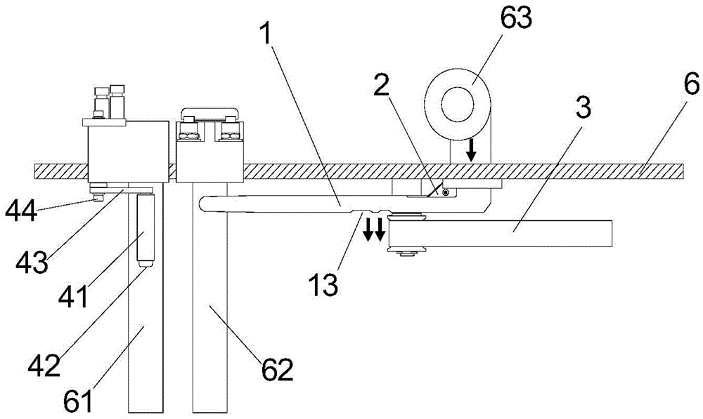
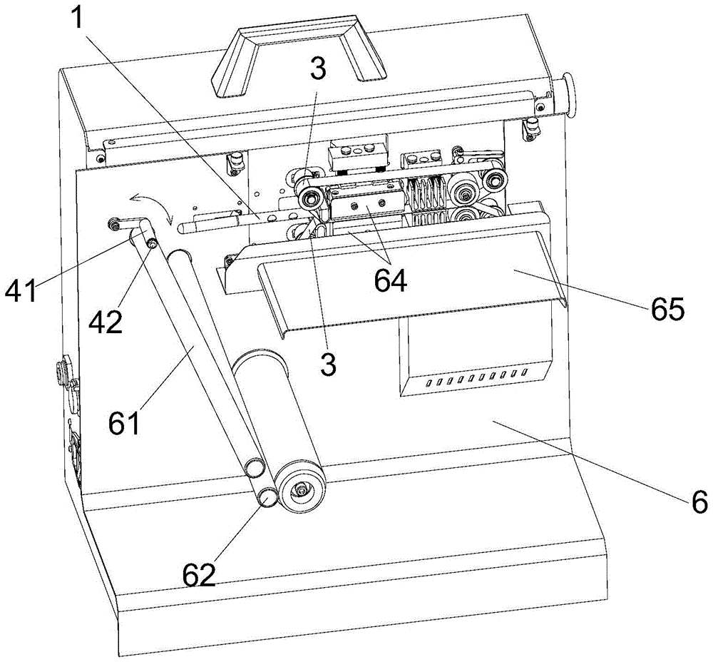
[0023] like Figure 1 to Figure 5 As shown, a new inflation structure for cushioning airbag inflators, including inflation guide rod 1, blade 2 and high temperature heating belt 3. In addition, a novel inflation structure for the cushion airbag inflator can also include the blockage wheel module 4 .

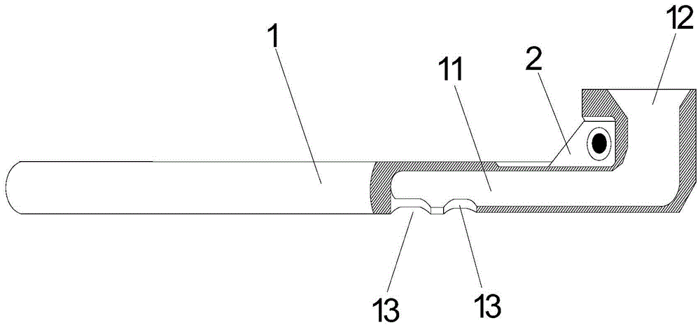
[0024] like figure 2 As shown, the interior of the inflatable guide rod 1 is formed with a gas channel 11, the right end of the inflatable guide rod 1 is formed with an air inlet 12 communicating with the gas channel 11, and the middle part of the inflatable guide rod 1 is formed with two gas outlets 13, and the gas outlet 13 communicates with the gas passage 11.

[0025] In ...


PUM


Abstract

The invention discloses a novel inflating structure for an airbag inflator. The novel inflating structure comprises an inflating guide rod, a blade and a high-temperature heating zone, wherein a gas channel is arranged inside the inflating guide rod; an air inlet is formed in one end of the inflating guide rod; at least one air outlet is formed in the inflating guide rod; the blade is arranged at the side of the inflating guide rod, and a cutting edge of the blade is close to the inflating guide rod; the inflating guide rod is arranged on the same horizontal position with the direction of an inlet of the high-temperature heating zone; and the inlet of the high-temperature heating zone is located between the air outlet and the blade. When an air cushion film is inflated by using the airbag inflator, the air cushion film is firstly inflated through an inflating inlet, is subjected to heat sealing by press-fit after entering the high-temperature heating zone from the inlet of the high-temperature heating zone and is incised by using the blade; and due to the adoption of an inflation, heat sealing by press-fit and incision inflating mode, the problem of gas leakage caused by heat sealing by press-fit after incision in the prior art can be effectively avoided, and the pressure of gas in the air cushion film can be ensured.

Description

technical field [0001] The invention relates to an inflatable structure, in particular to a novel inflatable structure for cushioning an airbag inflator. Background technique [0002] When the existing cushion air bag inflator (such as ZL201420412981.6) inflates the air cushion film, it first cuts the inflated air cushion film, and then presses and heat seals it. , part of the gas in the air cushion film will leak, and the pressure of the gas in the air cushion cannot be guaranteed, which will affect the cushioning effect of the air cushion film during the use of the air cushion. [0003] At the same time, when the existing cushion air bag inflator (such as ZL201420412981.6) inflates the air cushion film, the gas will run forward along the inflation channel connected between the two air cushion films, which will cause the uninflated air cushion The membrane bulges up prematurely and gets stuck on the upper film guide rod and the lower film guide rod of the cushion air bag i...

Claims


Application Information

Patent Timeline
Patent Type & Authority Applications(China)
IPC IPC(8): F17C5/00B31B1/64B31B1/04B31B1/74B31B1/22B31B50/04B31B50/22B31B50/64
CPCF17C5/00
Inventor 司匡书刘玉贵李渊司桂安
Owner HANGZHOU BINGJIA TECH
Why Eureka
Try Eureka