
Water cooling tank for vacuum oil purifier

A technology of vacuum oil purifier and cold water tank, applied in applications, household stoves, household heating, etc., can solve problems such as poor oil circuit and blockage of filter elements.

Inactive Publication Date: 2016-04-06
镇江市长江机电设备厂有限公司
View PDF0 Cites 2 Cited by
  • Summary
  • Abstract
  • Description
  • Claims
  • Application Information

AI Technical Summary

Problems solved by technology

[0003] The problem to be solved by the present invention is to install an anti-backflush filter, which cuts off the interlocking factors that may cause backflush, and automatically eliminates and restores restarts, such as filter blockage, poor oil passage, and alarm prompts.

Method used


Image

  • Water cooling tank for vacuum oil purifier
  • Water cooling tank for vacuum oil purifier

Examples


Embodiment Construction

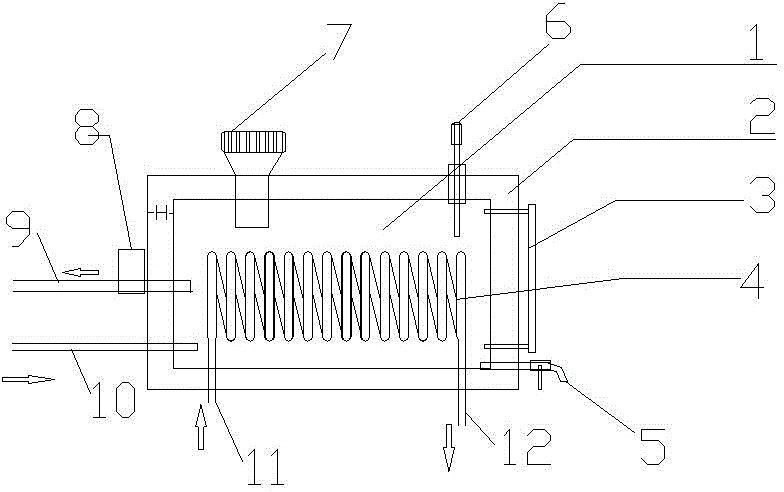
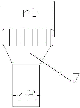
[0011] A cold water tank for a vacuum oil purifier, comprising a cold water tank 1, an anti-backflush filter 8, a water injection port 7, a temperature sensor 6, an insulation layer 2, a water level gauge 3, a condenser 4, a drain valve 5, and a water outlet pipe 9 With the water inlet pipe 10, a layer of insulation layer 2 is provided on the periphery of the cold water tank 1, the thickness of the insulation layer 2 is H, the water injection port 7 is located on the left side above the cold water tank 1, and the temperature sensor 6 is located on the right side above the cold water tank 1, the water level gauge 3 is fixed on the right side of the cold water tank 1, the drain valve 5 is located below the right side of the cold water tank 1, and the condenser 4 is sleeved on the cold water tank 1 Inside the tank 1, the inlet 11 and outlet 12 of the condenser 4 are located below the cold water tank 1, the water inlet pipe 10 is located below the left side of the cold water tank 1...


PUM


Abstract

The invention relates to a water cooling tank for a vacuum oil purifier. The water cooling tank comprises a water cooling tank body, an anti-backflow filter, a water filling nozzle, a temperature sensor, a heat preservation layer, a water level gauge, a condenser, a blow-down valve, a water outlet pipe and a water inlet pipe. The heat preservation layer is arranged on the periphery of the water cooling tank body. The water filling nozzle is located on the left side of the upper portion of the water cooling tank body. The temperature sensor is located on the right side of the upper portion of the water cooling tank body. The water level gauge is fixed to the right side of the water cooling tank body. The blow-down valve is located on the lower portion of the right side of the water cooling tank body. The condenser is sleeved with the water cooling tank body. Both an inlet and an outlet of the condenser are located in the lower portion of the water cooling tank body. The water inlet pipe is located on the lower portion of the left side of the water cooling tank body. The water outlet pipe is located on the upper portion of the left side of the water cooling tank body. The water outlet pipe is sleeved with the filter. Through the installation of the anti-backflow filter, various factors which can cause the backflow phenomenon are eliminated; in addition, fault removal and restarting can be conducted automatically, and intelligence is achieved.

Description

technical field [0001] The invention relates to a cold water tank, in particular to a cold water tank for a vacuum oil purifier. Background technique [0002] According to the characteristics of oil used in the metallurgical industry at home and abroad, with the participation of advanced technologies in various steel mills, power plants, mines, and oil stations, vacuum oil purifiers are launched to adapt to the above-mentioned developments and changes. The existing vacuum oil purifiers all have such a This feature, when the vacuum degree is not adjusted properly, the filter element is blocked, the oil discharge is not smooth, and the electronic control function fails, the oil will be directly sucked out of the vacuum tube, resulting in waste. Contents of the invention [0003] The problem to be solved by the present invention is to install an anti-backflush filter, which cuts off the interlocking factors that may cause backflush, and automatically eliminates and restores r...

Claims


Application Information

Patent Timeline
Patent Type & Authority Applications(China)
IPC IPC(8): F24C15/20
Inventor 张晓进
Owner 镇江市长江机电设备厂有限公司
Learn More