Control circuit and control method with self-adaptive blanking time

A control circuit and blanking time technology, applied in the direction of control/regulation system, electrical components, regulating electrical variables, etc., can solve the problems of not being able to fully characterize the magnitude of the peak current, detecting errors, and not being able to set the blanking time well

Inactive Publication Date: 2016-04-06
SILERGY SEMICON TECH (HANGZHOU) CO LTD
View PDF6 Cites 18 Cited by
  • Summary
  • Abstract
  • Description
  • Claims
  • Application Information

AI Technical Summary

Problems solved by technology

For the second method, in some control methods, the weight of the load cannot fully represent the magnitude of the peak current. For example, the power factor correction circuit using constant on-time control, when the load is constant, the peak current will also It increases with the increase of the input voltage. In this case, the blanking time cannot be set well depending on the weight of the load, and detection errors will also occur.

Method used


Image

  • Control circuit and control method with self-adaptive blanking time
  • Control circuit and control method with self-adaptive blanking time
  • Control circuit and control method with self-adaptive blanking time

Examples


Embodiment Construction

[0046] Several preferred embodiments of the present invention will be described in detail below with reference to the accompanying drawings, but the present invention is not limited to these embodiments. The present invention covers any alternatives, modifications, equivalent methods and schemes made on the spirit and scope of the present invention. In order to provide the public with a thorough understanding of the present invention, specific details are set forth in the following preferred embodiments of the present invention, but those skilled in the art can fully understand the present invention without the description of these details.

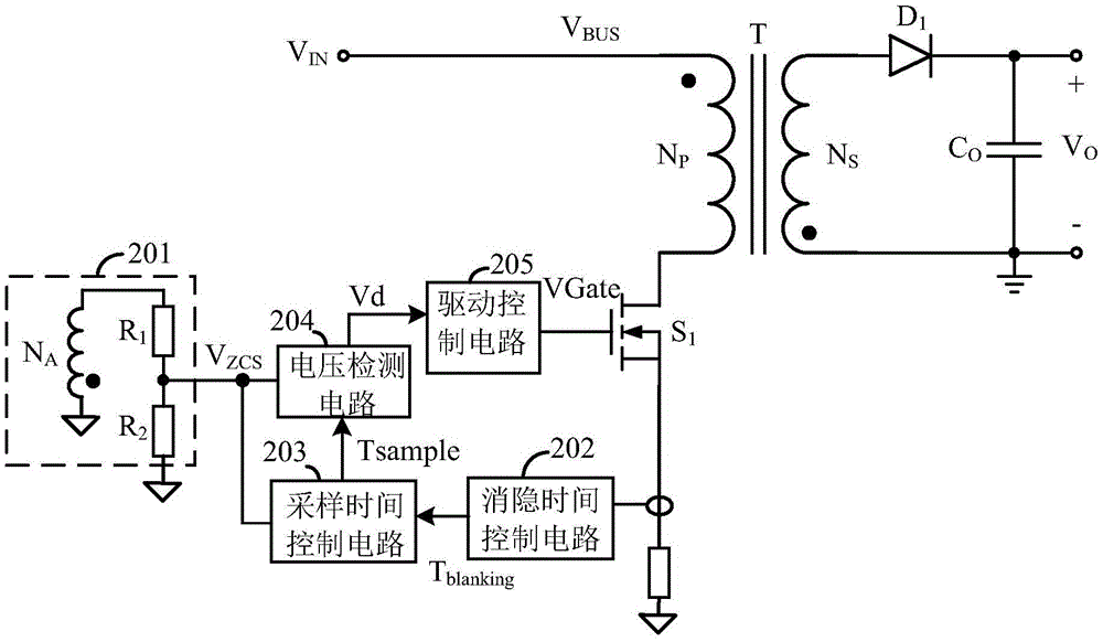
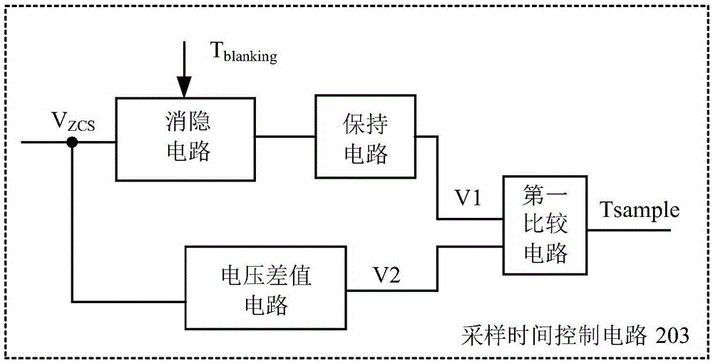
[0047] refer to figure 2 Shown is a structural diagram of a control circuit with an adaptive blanking time according to the present invention, figure 2 In the above, the control circuit is applied to the primary side feedback control of the flyback converter. In this embodiment, the flyback converter receives an input voltage signal V...


PUM


Abstract

The invention provides a control circuit and a control method with self-adaptive blanking time. The blanking time control circuit generates a blanking control signal according to current peak value of a main switch; the blanking control signal is used for controlling the blanking time in a feedback voltage signal sampling process, so that the blanking time can be changed along with the change of the current peak value of the main switch tube. According to the control circuit and the control method with the self-adaptive blanking time, accurate feedback and sampling can be realized without causing wrong detections; and in addition, the blanking time can be well controlled by the circuit according to actual changes, and the no-load loss is reduced.

Description

technical field [0001] The invention relates to the field of switching power supplies, more specifically, to a control circuit and control method with adaptive blanking time. Background technique [0002] In the flyback switching power supply, the output voltage is usually controlled by the feedback of the primary side, such as figure 1 It is a circuit frame diagram of the primary side feedback control of a flyback switching power supply in the prior art. The feedback signal representing the output voltage is obtained by coupling the auxiliary winding on the primary side with the secondary winding of the transformer, and the secondary side diode D1 When the freewheeling current is close to zero, the output voltage is proportional to the voltage of the auxiliary winding. At this time, the voltage of the auxiliary winding is sampled as the feedback signal of the output voltage, and the output voltage can be well controlled. The timing of sampling the voltage of the auxiliary ...

Claims


Application Information

Patent Timeline
Patent Type & Authority Applications(China)
IPC IPC(8): H02M3/335
CPCH02M3/33507H02M3/33523H02M1/0048Y02B70/10H02M3/335
Inventor 胡志亮白永江黄秋凯李乐
Owner SILERGY SEMICON TECH (HANGZHOU) CO LTD
Why Eureka
Try Eureka