Method for synchronizing vlan in a two-layer network, local switch and remote switch
A technology of local switches and Layer 2 networks, applied in the field of local switches and remote switches, can solve the problems of high error probability, high labor cost, low efficiency, etc., and achieve the effect of improving efficiency, saving labor cost, and eliminating error rate.
- Summary
- Abstract
- Description
- Claims
- Application Information
AI Technical Summary
Problems solved by technology
Method used
Image
Examples
Embodiment 1
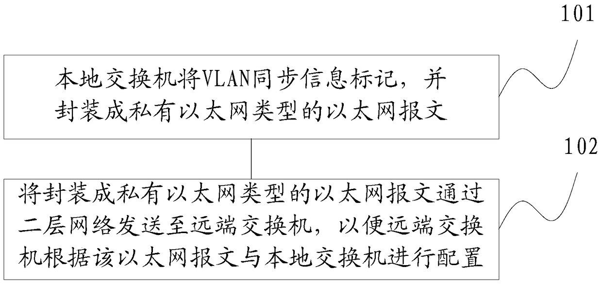
[0068] Such as figure 2 As shown, Embodiment 1 of the present invention provides a VLAN synchronization method in a two-layer network, and the method may include:
[0069] 101. The local switch marks the VLAN synchronization information and encapsulates it into an Ethernet packet of a private Ethernet type;
[0070] Step 101 may specifically be: the local switch adds the VLAN information to be sent to the packet sending port in the form of Tag;
[0071] The VLAN information that needs to be sent is encapsulated in Ethernet in a private format.
[0072] Table 1 shows the frame structure of the Ethernet packet encapsulated by the local switch:
[0073] Table 1
[0074] Destination MAC
Source MAC
802.1q
Tag label
private type
VLAN data
CRC
[0075] Table 2 shows the frame structure of private Ethernet type encapsulated by VLAN data:
[0076] Table 2
[0077]
[0078] Among them, the synchronization information that needs to be learne...
Embodiment 2
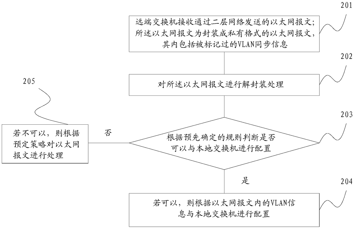
[0083] Such as image 3 As shown, the present embodiment takes the receiving end of the Ethernet message as the main body, and provides a VLAN synchronization method in a two-layer network, which method includes:
[0084] 201. The remote switch receives an Ethernet packet sent through a layer-2 network; the Ethernet packet is an Ethernet packet encapsulated in a private format, which includes tagged VLAN synchronization information;
[0085] The Ethernet message described in step 201 is the Ethernet message described in steps 101-102 of the first embodiment, and its encapsulation format and frame structure that can be adopted are the same as those of 101-102 of the first embodiment, and will not be repeated here. .
[0086] 202. Perform decapsulation processing on the Ethernet packet;
[0087] 203. Determine whether configuration with the local switch can be performed according to a predetermined rule;
[0088] The predetermined rule may specifically be: when the local swit...
Embodiment 3
[0108] Such as Figure 5 As shown, Embodiment 3 of the present invention provides a local switch, including:
[0109] A marking module 301, configured to mark VLAN synchronization information and encapsulate it into an Ethernet message of a private Ethernet type;
[0110] The sending module 302 is configured to send the Ethernet packet encapsulated into a private Ethernet type to the remote switch through the layer 2 network, so that the remote switch can configure with the local switch according to the Ethernet packet.
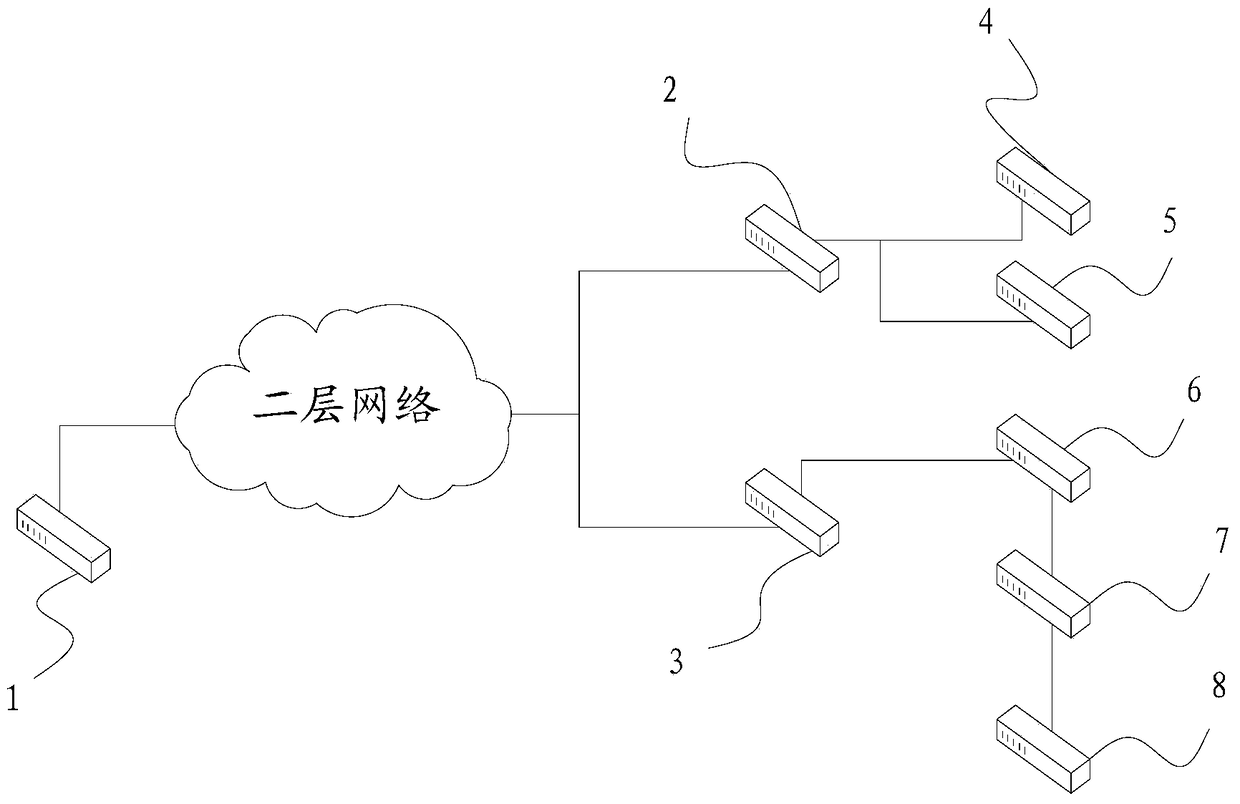
[0111]Further, the sending port of the local switch is added with the same domain name ID as the receiving port of the remote switch, wherein the local switch is configured as Server mode, and the remote switch is configured as Client mode, so that the switches at both ends can identify and forward Private Ethernet.
[0112] In a specific implementation, the marking module 301 in this embodiment is specifically used to add the VLAN information to be sent to...
PUM
 Abstract
Description
Claims
Application Information
 - R&D
- Intellectual Property
- Life Sciences
- Materials
- Tech Scout
- Unparalleled Data Quality
- Higher Quality Content
- 60% Fewer Hallucinations
Browse by: Latest US Patents, China's latest patents, Technical Efficacy Thesaurus, Application Domain, Technology Topic, Popular Technical Reports.
© 2025 PatSnap. All rights reserved.Legal|Privacy policy|Modern Slavery Act Transparency Statement|Sitemap|About US| Contact US: help@patsnap.com


