Mechanical hand clamp

A manipulator and fixture technology, applied in manipulators, chucks, manufacturing tools, etc., can solve the problems of low production efficiency, high positioning accuracy requirements, and high failure rate in the processing process, so as to improve work efficiency, continue to work efficiently, and reduce labor. The effect of consumption

Inactive Publication Date: 2016-04-13
CHANGZHOU JINGSHENG AUTOMATION TECH
View PDF8 Cites 1 Cited by
  • Summary
  • Abstract
  • Description
  • Claims
  • Application Information

AI Technical Summary

Problems solved by technology

[0003] The purpose of the present invention is to provide a manipulator fixture capable of solving the aforementioned problems in view of the problems of high positioning accuracy, high failure rate and low production efficiency of the manipulator described in the background technology when assembling mechanical equipment.

Method used


Image

  • Mechanical hand clamp
  • Mechanical hand clamp
  • Mechanical hand clamp

Examples


Embodiment Construction

[0017] Attached below Figure 1 to Figure 3 The present invention is set forth in detail:

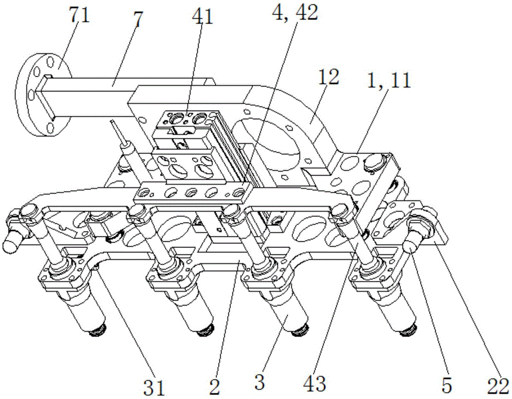
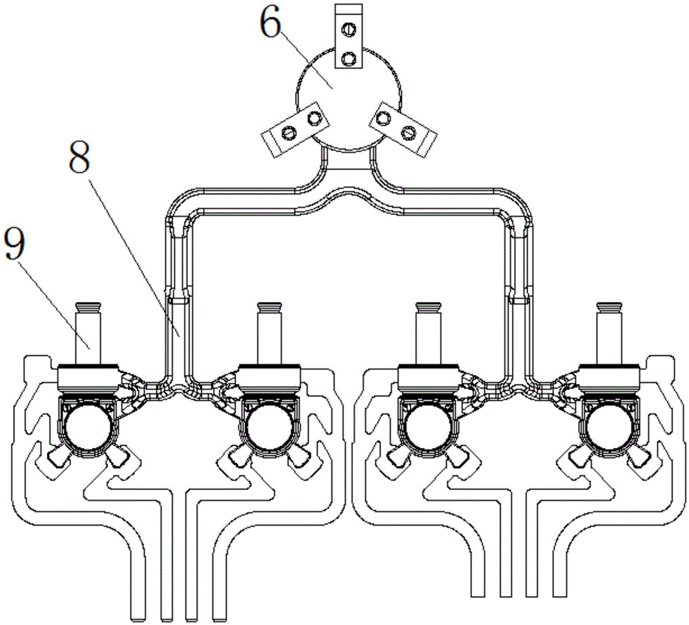
[0018] A gripper for a manipulator, which includes a connecting arm 7 , a connecting seat 1 , a floating seat 2 , a pick-up bucket 3 , an assembly assembly 4 , a positioning sensor 5 and an unloading assembly 6 .

[0019] The left end of the connecting arm 7 is provided with a flange 71 connected with the manipulator, and the right end of the connecting arm 7 is fixedly connected or integrally formed with the connecting seat 1 .

[0020] The connecting base 1 includes a bottom plate 11 and a rear side plate 12 , the bottom plate 11 and the rear side plate 12 are integrally formed or fixedly connected, and the four corners of the bottom plate 11 are provided with cylindrical through holes 13 .

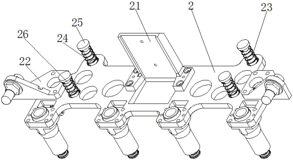
[0021] The floating seat 2 is arranged under the connecting seat 1, and the middle part of the floating seat 2 is provided with a mounting seat 21 for installing a lifting mechanism. The left s...


PUM


Abstract

The invention relates to a mechanical hand clamp which comprises a connecting seat, a floating seat, piece taking cylinders, an assembling assembly and locating sensors. The floating seat is connected to the position below the connecting seat in a floating manner. The multiple piece taking cylinders are fixed to the front side of the floating seat side by side at certain intervals. The assembling assembly comprises a lifting seat, a beam and ejection rods which are connected to the front side of the beam and are opposite to the piece taking cylinders. The lifting seat drives the ejector rods through the beam to enter the corresponding piece taking cylinders so that rods sucked by the piece taking cylinders can be ejected out of the piece taking cylinders to be assembled into corresponding assembling holes in a semi-finished piece. The locating sensors are arranged on the floating seat.

Description

technical field [0001] The invention relates to the field of electromechanical automation, in particular to a manipulator clamp. Background technique [0002] The manipulator is an electromechanical device that realizes mechanized and automated production. The manipulator can replace the heavy labor of people and can operate in a harmful environment. Therefore, it is widely used in the fields of machinery manufacturing, metallurgy, electronics, light industry and atomic energy. In the field of mechanical assembly, manipulators can replace manpower to complete the assembly of mechanical equipment. However, in mechanical assembly, if the positioning cannot be accurately positioned, the failure rate of the assembly process is high, and manual troubleshooting is required, and the production efficiency will be greatly reduced. Quality problems will also occur, therefore, special manipulator fixtures need to be designed to solve the above problems. Contents of the invention [...

Claims


Application Information

Patent Timeline
Patent Type & Authority Applications(China)
IPC IPC(8): B25J15/06B25J13/08
CPCB25J13/088B25J15/0616
Inventor 金加法徐晓东高庆强
Owner CHANGZHOU JINGSHENG AUTOMATION TECH
Why Eureka
Try Eureka