Manipulator

A technology of manipulators and inflators, applied in the field of manipulators, can solve problems such as being easily pinched or deformed

Inactive Publication Date: 2016-04-13
昆山—邦泰汽车零部件制造有限公司
View PDF11 Cites 8 Cited by
  • Summary
  • Abstract
  • Description
  • Claims
  • Application Information

AI Technical Summary

Problems solved by technology

Most of the existing manipulators are used to pick up the product. If the material is brittle or soft, it is easy to be damaged or deformed. Therefore, the market needs a device that can avoid damage to the device and is suitable for various specifications. manipulator

Method used


Image

  • Manipulator
  • Manipulator

Examples


Embodiment Construction

[0019] The present invention will be specifically introduced below in conjunction with the accompanying drawings and specific embodiments.

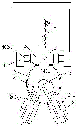
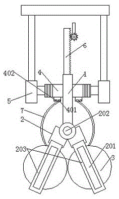
[0020] The manipulator includes: a connecting rod 1, a splint 2 fixed under the connecting rod 1, a balloon 3 which is set on the hollow part 201 on the splint 2 and clamps the device, fixed on both sides of the connecting rod 1 and connected to the filling and discharging of the balloon 3 The air assembly is connected to the limit rod 8 on the connecting rod 1, the gear 9 that is clamped to the limit rod 8 and drives the above limit rod 8 to move up and down, and the rotating motor connected to the gear 9. The limit rod 8 is provided with Snap teeth arranged in rows. The rotating motor drives the gear 9 to rotate, thereby driving the clamping teeth to move, thereby driving the limit rod 8 to move; the gear 9 rotates clockwise, the limit rod 8 moves upward, and the gear 9 rotates counterclockwise, the limit rod 8 moves downward.

[0021]...


PUM


Abstract

The invention discloses a manipulator. The manipulator comprises a connecting rod, a clamping plate fixed to the lower side of the connecting rod, a balloon which is arranged on the hollow portion of the clamping plate and clamps devices, inflation and deflation components fixed to the two sides of the connecting rod and connected to the balloon, a limiting rod connected to the connecting rod, a gear which is clamped onto the limiting rod and drives the limiting rod to move up and down, and a rotary motor connected to the gear. The manipulator can not damage the devices and is suitable for devices in various specifications, and the distance between the manipulator and the devices can be adjusted.

Description

technical field [0001] The invention relates to the field of mechanical automation, in particular to a manipulator. Background technique [0002] The manipulator is an automatic operating device that can imitate certain movement functions of the human hand and arm, and is used to grab, carry objects or operate tools according to a fixed program. The manipulator is the earliest industrial robot and the first modern robot. It can replace the heavy labor of people to realize the mechanization and automation of production, and can operate in harmful environments to protect personal safety. Therefore, it is widely used in machinery manufacturing, metallurgy, Departments of electronics, light industry and atomic energy. Most of the existing manipulators are used to pick up the product. If the material is brittle or soft, it is easy to be damaged or deformed. Therefore, the market needs a device that can avoid damage to the device and is suitable for various specifications. manip...

Claims


Application Information

Patent Timeline
Patent Type & Authority Applications(China)
IPC IPC(8): B25J15/12
CPCB25J15/12
Inventor 郑坚雄
Owner 昆山—邦泰汽车零部件制造有限公司
Why Eureka
Try Eureka