Ink bottle

An ink bottle and bottle body technology, applied in the field of school supplies, can solve the problems of excessive wall thickness, easy to get dirty, ink sucking, etc., and achieve the effect of small liquid level rise

Inactive Publication Date: 2016-04-13
王刚
View PDF8 Cites 5 Cited by
  • Summary
  • Abstract
  • Description
  • Claims
  • Application Information

AI Technical Summary

Problems solved by technology

[0002] Fountain pens are widely used in our daily life. As a supporting product for pens, the amount of ink used is also very considerable. However, when there is little ink, the pen cannot suck out the ink in the bottle. If you buy a new one of a different brand If you use different inks, you cannot pour the remaining ink into a new ink bottle; because different brands of inks are colloids with different charges, which will cause precipitation, and even block the ink outlet of the pen and

Method used


Image

  • Ink bottle
  • Ink bottle
  • Ink bottle

Examples


Embodiment 1

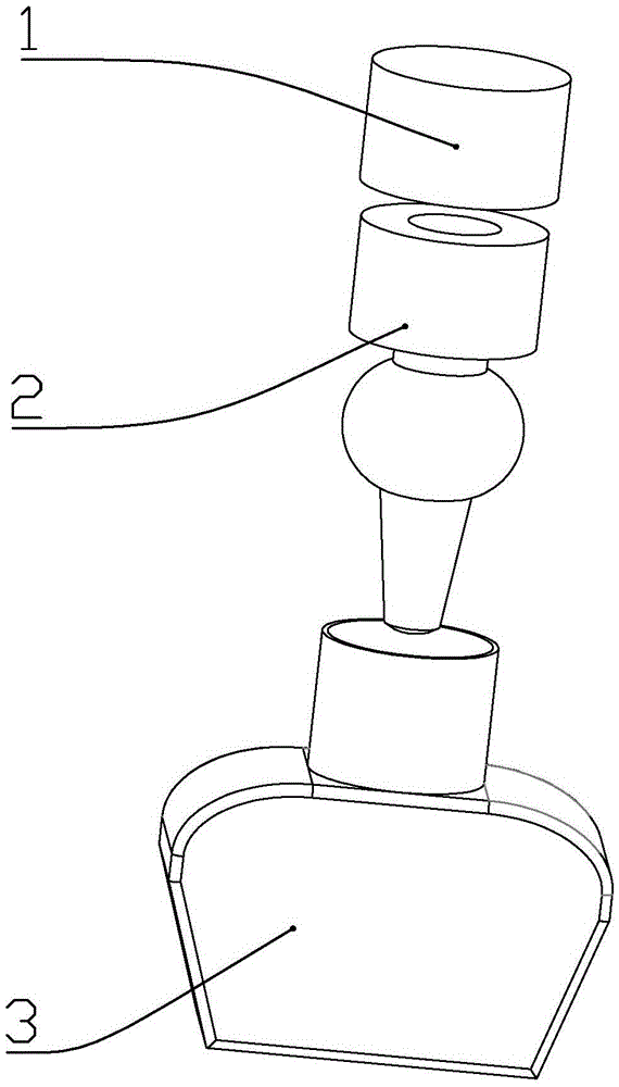
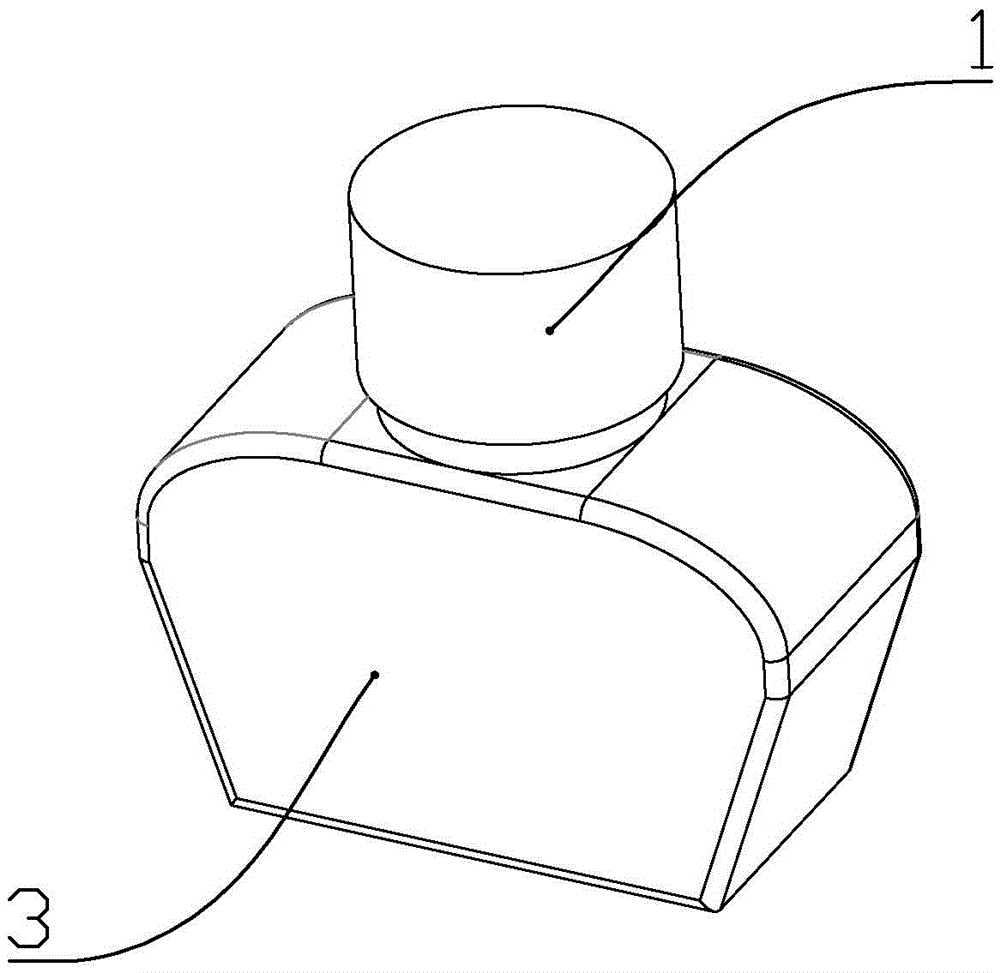
[0024] according to Figure 1 to Figure 8 As shown, an ink bottle described in this embodiment includes a bottle body 3, a bottle mouth 31 and a bottle cap 1 used in conjunction with the bottle mouth are formed on the upper part of the bottle body;

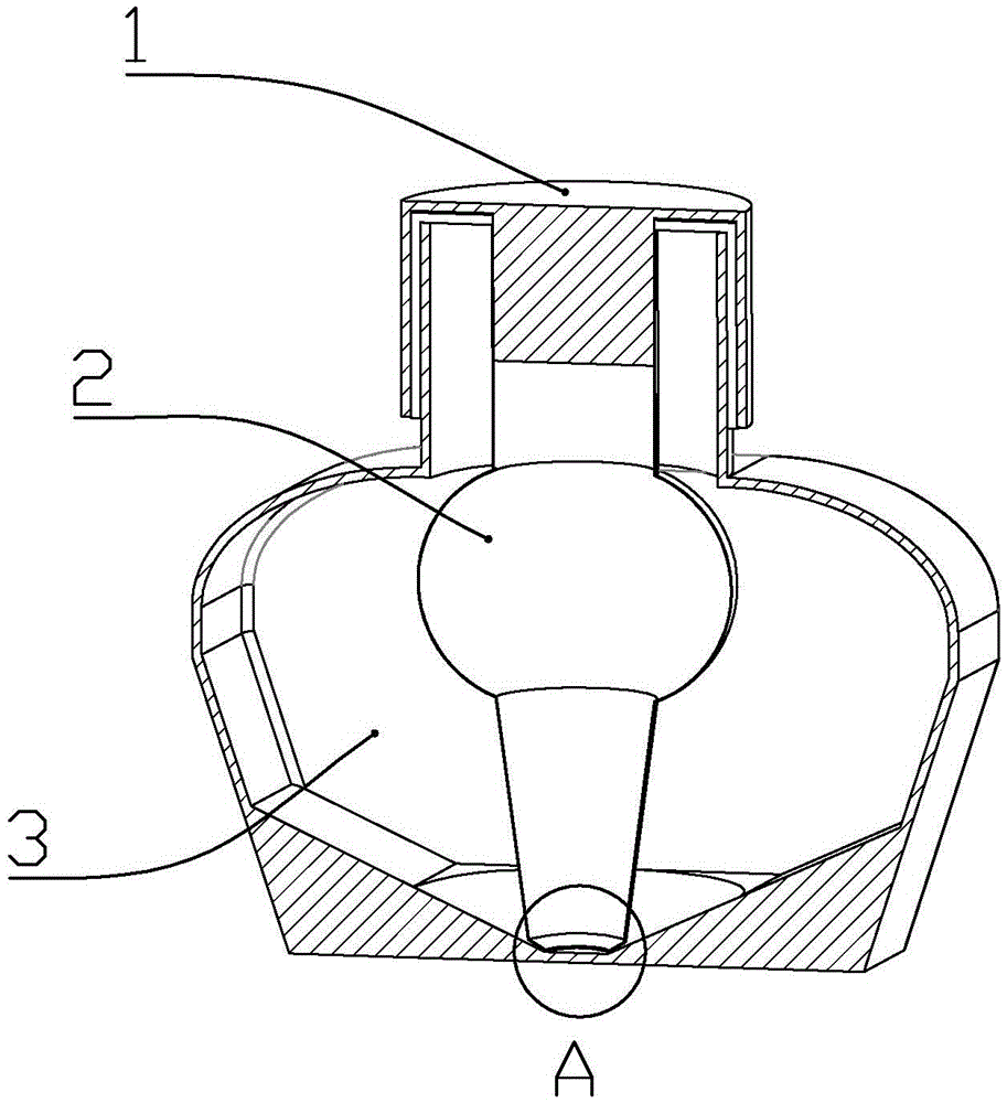
[0025] It also includes an inner bottle 2; the inner bottle is sequentially from top to bottom a bottle mouth matching part 21, a cavity A22, a spherical cavity 23, a cavity B24, and a flow blocking wall 25; the bottle mouth matching part and the bottle The mouth is connected by thread fit, and the cavity A is a cylindrical cavity as a whole, and its inner diameter is 16mm; the cavity A and the spherical cavity are connected with each other, and the radius of the spherical cavity is the radius of the cavity A. 2.3-3 times of that, the spherical cavity and the cavity B communicate with each other, and the cavity B as a whole is a circular platform with a large upper part and a smaller lower part. The radius of the upper bottom surf...

Embodiment 2

[0033] according to Figure 1 to Figure 6 , Figure 8 , Figure 9 As shown, an ink bottle described in this embodiment includes a bottle body 3, a bottle mouth 31 and a bottle cap 1 used in conjunction with the bottle mouth are formed on the upper part of the bottle body;

[0034] It also includes an inner bottle 2; the inner bottle is sequentially from top to bottom a bottle mouth matching part 21, a cavity A22, a spherical cavity 23, a cavity B24, and a flow blocking wall 25; the bottle mouth matching part and the bottle The mouth is used in conjunction with threads, and the cavity A is a cylindrical cavity as a whole, and its inner diameter is 16mm; the cavity A and the spherical cavity communicate with each other, and the radius of the spherical cavity is the radius of the cavity A 2.3-3 times of that, the inner lower part of the spherical cavity is formed with an annular protrusion 27, and the lower part of the annular protrusion is provided with at least 3 small holes;...


PUM

PropertyMeasurementUnit
The inside diameter ofaaaaaaaaaa
Heightaaaaaaaaaa
Radiusaaaaaaaaaa

Abstract

An ink bottle comprises a bottle body and a bottle cap and further comprises an inner bottle body. The inner bottle body is sequentially provided with a bottle opening matching part, a cavity A, a spherical cavity, a cavity B and a flow stop wall from top to bottom. The cavity A is a cylindrical cavity overall, the spherical cavity is communicated with the cavity B, and the flow stop wall is arranged at the lower portion of the cavity B and is soft. The flow stop wall is annular, the inner circumference is lower than the outer circumference, and a round hole is formed in the lower portion of the flow stop wall. A bottom plane is formed at the bottom of the inner side of the bottle body and provided with a conic face, and a slope face is arranged on the conic face. The lowest end of the slope face and the highest end of the conic face are located in the same horizontal position. The lowest end of the conic face and the bottom plane are located in the same horizontal position. A gap is formed between the flow stop wall and the conic face. The inner diameter of the bottle cap is equal to the outer diameter of the bottle opening matching part of the inner bottle body, and a protrusion is formed in the bottle cap.

Description

technical field [0001] The invention belongs to school supplies, in particular to an ink bottle. Background technique [0002] Fountain pens are widely used in our daily life. As a supporting product for pens, the amount of ink used is also very considerable. However, when there is little ink, the pen cannot suck out the ink in the bottle. If you buy a new one of a different brand If you use different inks, you cannot pour the original remaining ink into a new ink bottle; because different brands of inks are colloids with different charges, which will cause precipitation, and even block the ink outlet of the pen and cause the pen to be scrapped. [0003] Patent No. 200810196964.2 discloses an ink bottle, which is provided with a circular groove in the middle of the bottom; the circular groove can make the ink in the bottle concentrate in the groove until it is used up when at least ink is used. It has the effect of saving and reducing pollution, but the wall thickness of th...

Claims


Application Information

Patent Timeline
IPC IPC(8): B43L25/04
CPCB43L25/04
Inventor 李峰
Owner 王刚
Why Eureka
Try Eureka