Supercharge Your Innovation With Domain-Expert AI Agents!

Movable energy storage vehicle

A mobile energy storage and compartment technology, applied in the field of mobile energy storage vehicles, can solve problems such as difficult to quickly replace battery packs, lack of humanization, poor mobility, etc., to facilitate field operations, solve field water difficulties, and have good heat dissipation conditions Effect

Inactive Publication Date: 2016-04-13
SHANGHAI SAFEGREEN TECH
View PDF4 Cites 0 Cited by
  • Summary
  • Abstract
  • Description
  • Claims
  • Application Information

AI Technical Summary

Problems solved by technology

[0002] At present, a mobile energy storage station is disclosed on the market. Its structural characteristics are: it is composed of a container shell, a battery pack, a control cabinet and a converter cabinet. The container shell is divided into three parts: the machine room, the power distribution room and the work room. Part, the power distribution room is set at the rear of the container shell, the work room is set at the front of the container shell, and the machine room is set between the power distribution room and the work room, and the battery pack and the converter cabinet are installed in the machine room , the control cabinet is installed in the work room, and the power distribution cabinet is installed in the power distribution room. However, since the machine room of this structure is not equipped with an inspection door that communicates with the outside world, it is difficult to quickly replace the damaged battery pack. In addition, due to the use of containers, the heat dissipation conditions are poor, and at the same time, the mobility is also poor.
[0003] This kind of mobile energy storage equipment is often used in some relatively remote places, which will bring a lot of inconvenience to the life of the staff, especially the problem of people going to the toilet. In some relatively remote places, this problem plagues It is very embarrassing for many people, especially women, and the existing mobile energy storage stations are only working hard on how to better store energy. They often lack consideration for this kind of humanized issues, and at our level of civilization In an increasingly advanced society, this kind of thinking needs to be changed

Method used


Image

  • Movable energy storage vehicle
  • Movable energy storage vehicle

Examples


Embodiment Construction

[0017] The following will clearly and completely describe the technical solutions in the embodiments of the present invention with reference to the accompanying drawings in the embodiments of the present invention. Obviously, the described embodiments are only some, not all, embodiments of the present invention. Based on the embodiments of the present invention, all other embodiments obtained by persons of ordinary skill in the art without making creative efforts belong to the protection scope of the present invention.

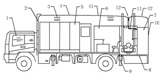
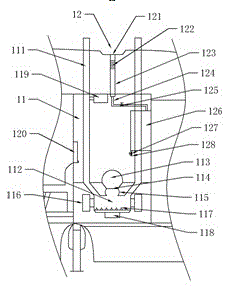
[0018] see Figure 1~2 , in an embodiment of the present invention, a mobile energy storage vehicle includes a cab 1, a compartment 4 and a vehicle chassis 8, the cab 1 is connected to the vehicle chassis 8, and the compartment 4 is fixedly installed on the vehicle chassis 8, and the compartment 4 The interior of the car is equipped with a machine room 5 for installing battery packs, a work room 6 for installing monitoring equipment, a toilet 11 that can colle...


PUM


Abstract

The invention discloses a movable energy storage vehicle which comprises a cab, a carriage and a vehicle chassis, wherein the cab is connected with the vehicle chassis; the carriage is fixedly installed on the vehicle chassis; a machine room for installing battery packs, a work room for installing monitoring equipment, a toilet capable of collecting water and used for people to defecate as well as a power distribution room of cable coils are arranged in the carriage; the machine room is arranged at the front part of the carriage; the work room and the toilet are adjacently arranged at the middle part of the carriage; the power distribution room is arranged at the tail of the carriage; and heat dissipation vents are arranged above the machine room, the work room and the power distribution room and at the top of the carriage. By virtue of the carriage, damaged battery packs can be quickly replaced flexibly, and heat dissipation conditions are good; meanwhile, by virtue of the arrangement of the toilet, the humanization of the whole movable energy storage vehicle is greatly increased, and the field operation of people is facilitated; and by utilizing the top of the carriage and a water collecting device for collecting water, rainwater is fully utilized, so that the problem of difficulty of water utilization in fields can be solved to a certain degree.

Description

technical field [0001] The invention relates to the field of energy equipment, in particular to a mobile energy storage vehicle. Background technique [0002] At present, a mobile energy storage station is disclosed on the market. Its structural characteristics are: it is composed of a container shell, a battery pack, a control cabinet and a converter cabinet. The container shell is divided into three parts: the machine room, the power distribution room and the work room. Part, the power distribution room is set at the rear of the container shell, the work room is set at the front of the container shell, and the machine room is set between the power distribution room and the work room, and the battery pack and the converter cabinet are installed in the machine room , the control cabinet is installed in the work room, and the power distribution cabinet is installed in the power distribution room. However, since the machine room of this structure is not equipped with an inspe...

Claims


Application Information

Patent Timeline
Patent Type & Authority Applications(China)
IPC IPC(8): B60P3/00B60R15/04H02B1/52
CPCB60P3/00B60R15/04H02B1/52
Inventor 詹胜
Owner SHANGHAI SAFEGREEN TECH
Features
  • R&D
  • Intellectual Property
  • Life Sciences
  • Materials
  • Tech Scout
  • Unparalleled Data Quality
  • Higher Quality Content
  • 60% Fewer Hallucinations
Learn More