Hot-embossing tool rest device

A frame device and flower knife technology, applied in textile and papermaking, fabric surface trimming, thorn pattern, etc., can solve the problems of poor quality of hot embossed products, reduced life of upper knife rollers, insufficient cylinder output, etc., to facilitate the maintenance of equipment. , the effect of reducing the beating amplitude and reducing the force

Inactive Publication Date: 2016-04-13
QUANZHOU HANWEI MACHINERY MFG
View PDF3 Cites 0 Cited by
  • Summary
  • Abstract
  • Description
  • Claims
  • Application Information

AI Technical Summary

Problems solved by technology

[0002] At present, the relevant hot embossing knife holder device used in domestic diaper machinery, sanitary napkin machinery, mattress machinery and other equipment is that the lower knife roller is fixed on the base of the knife holder, the upper knife roller is set on the upper part of the knife holder, and the upper knife roller Use the air cylinder to pressurize the upper knife roller to maintain a certain pressure on the lower knife roller. There is an adjusting slant block between the two knife rollers to adjust the gap between the two knife rollers; the knife holder uses the air cylinder to pressurize the upper knife roller. The air cylinder used by the knife holder to pressurize the upper knife roller and the cylinder on the main line share the same air intake pipe, which makes the air pressure of the cylinder of the knife holder face unstable. As a result, the output of the cylinder will be insufficient and unstable, resulting in actual In use, the upper knife roller jumps under microscopic conditions; in addition, the gravity of the upper knife roller itself is superimposed on the pressure of the cylinder, so that according to the relationship between the action force and the reaction force, the bearing force of the upper knife roller will be greatly increased, and the service life will be reduced, and the use effect will be poor. The hot embossed products produced by this related equipment are of poor quality and low yield, which greatly increases the production cost of the enterprise

Method used


Image

  • Hot-embossing tool rest device
  • Hot-embossing tool rest device

Examples


Embodiment Construction

[0012] The present invention will be further described in conjunction with the accompanying drawings and specific embodiments.

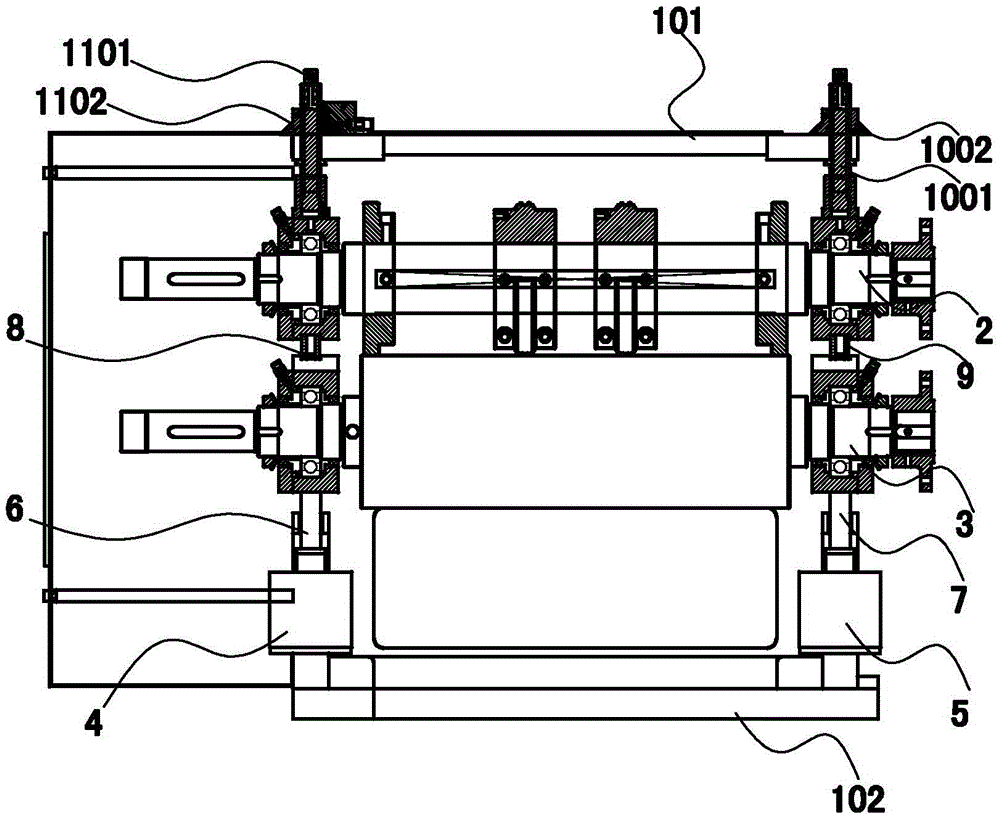
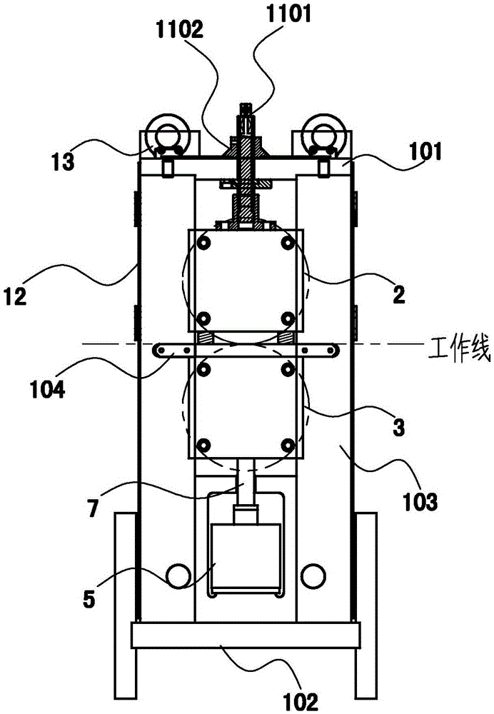
[0013] refer to figure 1 , figure 2 , the preferred hot embossing knife rest device of the present invention includes a knife rest, an upper knife roller assembly 2, a lower knife roller assembly 3, a first pushing mechanism 4, a second pushing mechanism 5, a first guide rod 6, a first Two guide rods 7, the first spring 8, the second spring 9, the first adjustment mechanism, the second adjustment mechanism, the protective cover 12 and four lifting bolts 13, the knife rest includes an upper top plate 101, a base 102, a left side plate , the right side plate 103 and the fixed supporting plate 104, one end of the left side plate and one end of the right side plate 103 are fixed on the base 102, the other end of the left side plate and the other end of the right side plate 103 are connected with the upper top plate 101 respectively The two ends are fi...


PUM


Abstract

The invention relates to the field of hygienic product equipment, and provides a hot-embossing tool rest device. The hot-embossing tool rest device comprises a tool rest, an upper tool roller assembly, a lower tool roller assembly, a first pushing mechanism, a second pushing mechanism, a first guide rod, a second guide rod, a first spring, a second spring, a first adjusting mechanism and a second adjusting mechanism. The two ends of the upper tool roller assembly are connected with the first adjusting mechanism and the second adjusting mechanism respectively and arranged between a left side plate and a right side plate in the mode of being capable of being adjusted in the vertical direction. The end, on the left side plate, of the upper tool roller assembly is flexibly connected with the left end of the lower tool roller assembly in the vertical direction through the first spring. The end, on the right side plate, of the upper tool roller assembly is flexibly connected with the right end of the lower tool roller assembly in the vertical direction through the second spring. The hot-embossing tool rest device solves the problem that an existing hot-embossing tool rest device is not stable in structure, short in service life and the like.

Description

technical field [0001] The invention relates to the field of sanitary products, in particular to a hot embossing knife holder device. Background technique [0002] At present, the relevant hot embossing knife holder device used in domestic diaper machinery, sanitary napkin machinery, mattress machinery and other equipment is that the lower knife roller is fixed on the base of the knife holder, the upper knife roller is set on the upper part of the knife holder, and the upper knife roller Use the air cylinder to pressurize the upper knife roller to maintain a certain pressure on the lower knife roller. There is an adjusting slant block between the two knife rollers to adjust the gap between the two knife rollers; the knife holder uses the air cylinder to pressurize the upper knife roller. The air cylinder used by the knife holder to pressurize the upper knife roller and the cylinder on the main line share the same air intake pipe, which makes the air pressure of the cylinder ...

Claims


Application Information

Patent Timeline
Patent Type & Authority Applications(China)
IPC IPC(8): D06C23/04
CPCD06C23/04
Inventor 林秉正林妍盈
Owner QUANZHOU HANWEI MACHINERY MFG
Why Eureka
Try Eureka