Winding machine

A technology of winding machine and unwinding mechanism, which is applied in the direction of winding strips, thin material processing, transportation and packaging, etc. It can solve the problems of small number of transport wheels, tight or too loose mica tape, and exceeding the winding range, etc. Achieve the effects of reducing the jumping range, improving the stress condition, the fit condition and the flatness of the end surface

Inactive Publication Date: 2020-09-11
PAMICA TECH CORP
View PDF5 Cites 0 Cited by
  • Summary
  • Abstract
  • Description
  • Claims
  • Application Information

AI Technical Summary

Problems solved by technology

[0004] 1. The overall degree of automation of the equipment is not high, and manual assistance is still required to connect the tape, which wastes labor costs
[0005] 2. In the winding stage, the raw materials cannot be locked well, resulting in the problem that the raw materials are detached during the work process
[0006] 3. In the process of feeding, due to the problem of tension, the mica tape is often too tight or too loose. After a period of use, the mica tape will break away from the existing delivery line.
[0007] 4. The problem of feeding angle cannot be solved when feeding, which will lead to the inability to transport stably, and there are few types of suitable products
[0008] 5. During the feeding process, due to the problem of the swing range, the mica tape cannot be transported stably
[0009] 6. The fixed-width grooved wheels are used in the actual transportation process, which need to be configured with more than 20 specifications, which is costly and requires a complete replacement, which is very troublesome
[0010] 7. The mica tape is a kind of flexible material. In the process of transportation, because there is no restriction on its axial movement, it will make it exceed the winding range, and the products produced cannot meet the requirements in appearance and use.
[0011] 8. The rewinding of the existing equipment on the rewinding side is uncoordinated, and manual assisted rewinding is often required, which is extremely inconvenient
[0012] 9. The existing winding equipment has a small number of transport wheels, not to mention few functions, and the layout is not harmonious, which cannot ensure the stable transport of the mica tape

Method used


Image

  • Winding machine
  • Winding machine
  • Winding machine

Examples


Embodiment 1

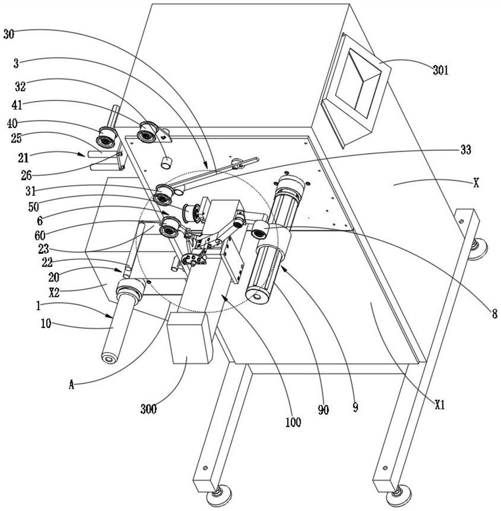
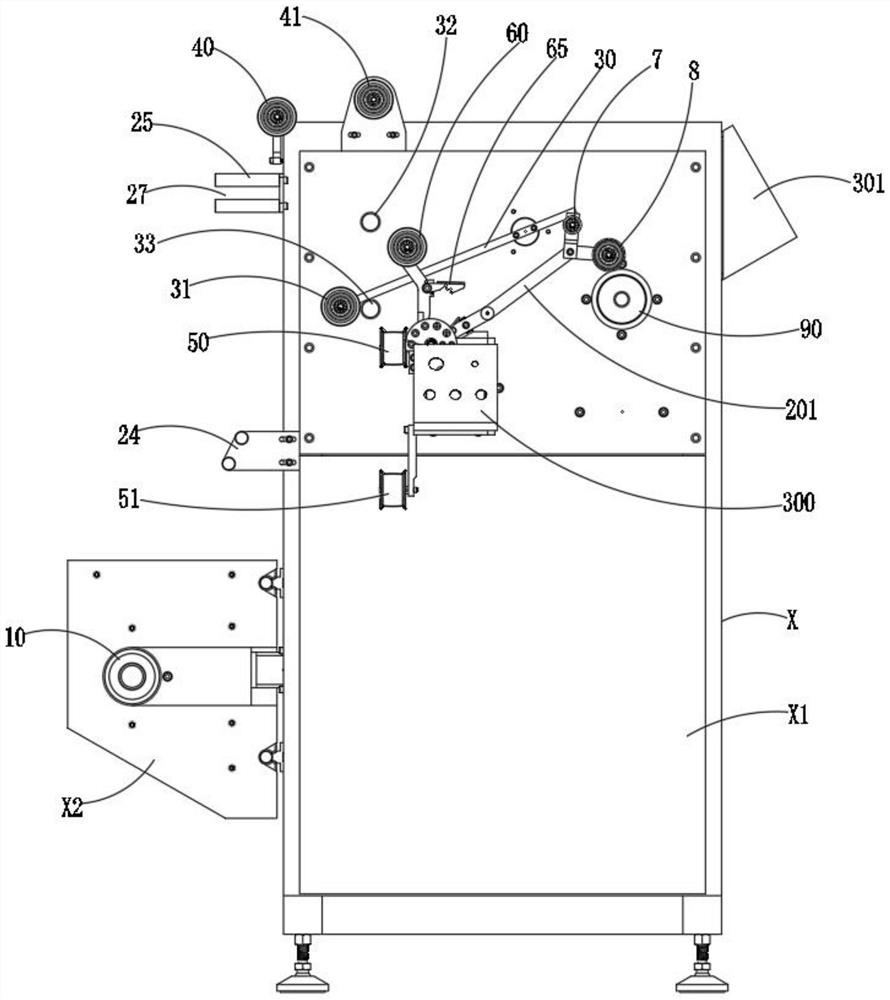
[0041] As an optimization scheme of the embodiment of the present invention, please refer tofigure 1 , figure 2 and image 3 , the unwinding mechanism 1 includes a placement shaft 10 for placing raw materials and a locking member 11 for locking raw materials on the placement shaft 10, and the placement shaft 10 is installed on the vertical installation surface of the machine body X On X1, the locking member 11 is installed on the installation shaft 10 . In this embodiment, the locking of the raw material can be ensured by arranging the shaft 10 and the locking member 11, so as to avoid the problem that the raw material is detached during the working process, which will affect the feeding.

[0042] To further optimize the above scheme, please refer to figure 1 , figure 2 , image 3 and Figure 4 , the placement shaft 10 includes a shaft body for the raw material sleeve, the shaft body is installed on the body X, and the end of the shaft body far away from the body X is p...

Embodiment 2

[0047] As an optimization scheme of the embodiment of the present invention, please refer to figure 1 and image 3 , the clipping mechanism includes a first clipping assembly 20 for the first clipping, the first clipping assembly 20 includes two parallel first optical axes 22 and two first optical axes 22, the first mounting plate 23 is installed, and the first mounting plate 23 is fixed on the body X. The interval between the two first optical axes 22 is the first limit for the mica tape to pass through. Range 24. In this embodiment, the limiting method is limited by the distance between the two first optical axes 22, so as to limit the swing amplitude of the mica tape within this range. Preferably, the two first optical axes 22 are parallel to the shaft body of the installation shaft 10 .

[0048] As an optimization scheme of the embodiment of the present invention, please refer to figure 1 and image 3 , the limiting mechanism also includes a second limiting component ...

Embodiment 3

[0053] As an optimization scheme of the embodiment of the present invention, please refer to figure 1 and image 3 , the buffer device 3 includes a movable rod 30 that can swing back and forth and a buffer roller 31 that is partially wrapped by the mica tape, and the position that the mica tape is wrapped on the buffer roller 31 is located Below, and the buffer roller 31 is installed on one end of the movable rod 30, the other end of the movable rod 30 is hinged on the body X, and the movable rod 30 is installed on the buffer roller 31 The swing track at one end is consistent with the direction in which the mica tape is transported. In this embodiment, the mica tape will lift the buffer roller 31 upwards, and it will sink due to gravity, so it can play a buffering effect and play the function of real-time tensioning of the mica tape. Preferably, the buffer device 3 further includes a driving member for driving the movable rod 30 to move. The driving method can be gravity si...


PUM


Abstract

The invention relates to a winding machine. The winding machine comprises a machine body and further comprises an unwinding mechanism for allowing a raw material to be placed, an amplitude limiting mechanism for limiting the swing amplitude of a mica tape, a buffering device for adjusting the tensioning degree of the mica tape, an angle adjusting device for adjusting the feeding angle of the micatape, and a winding mechanism for winding the mica tape; the unwinding mechanism, the amplitude limiting mechanism, the buffering device, the angle adjusting device and the winding mechanism are arranged in the mica tape conveying direction in sequence. According to the winding machine, the swing amplitude of the mica tape in the feeding process can be limited through the amplitude limiting mechanism, and accordingly, it is ensured that the mica tape is stably conveyed; the tensioning degree of the mica tape can be adjusted through the buffering device, the mica tape tensioning effect is achieved, and the situation that the mica tape is too tight or too loosen and deviates from an existing conveying line is avoided; and the feeding angle of the mica tape can be adjusted through the angle adjusting device, thus, the mica tape can be stably conveyed, and the winding machine is suitable for multiple types of products.

Description

technical field [0001] The invention relates to the technical field of mica tape winding, in particular to a winding machine. Background technique [0002] Early products such as mica tape used a single plate, and its length was mostly between 500 and 1000m. It was very troublesome to use manual frequent splicing. [0003] In the prior art, it is considered to use a machine to wind the tape to replace the manual tape, but in the actual application process, various problems often occur. For example: [0004] 1. The overall degree of automation of the equipment is not high, and manual assistance is still required to connect the tape, which wastes labor costs. [0005] 2. In the winding stage, the raw materials cannot be locked well, resulting in the problem of raw materials falling off during the working process. [0006] 3. In the process of feeding, due to the problem of tension, the mica tape is often too tight or too loose. After a period of use, the mica tape will brea...

Claims


Application Information

Patent Timeline
Patent Type & Authority Applications(China)
IPC IPC(8): B65H23/188B65H23/26B65H23/032B65H75/24
CPCB65H23/032B65H23/1888B65H23/26B65H75/243B65H2701/1133
Inventor 潘渡江李新辉李俊吴新军柳辉
Owner PAMICA TECH CORP
Why Eureka
Try Eureka