Method for hoisting inclining shuttle-shaped space truss

A technology of space truss and hoisting method, which is applied in the direction of construction, building structure, and building material processing, etc., which can solve the problems of large distance between hoisting points, increased stress on slings, and increased difficulty of reinforcement, etc., to achieve security Safety and reliability, lower hoisting height, lower lifting performance

Active Publication Date: 2016-04-13
CHINA CONSTR SCI & IND CORP LTD
View PDF3 Cites 6 Cited by
  • Summary
  • Abstract
  • Description
  • Claims
  • Application Information

AI Technical Summary

Problems solved by technology

Single machine hoisting of large-span structures has the following disadvantages: 1) The length of the truss is long and the distance between the hoisting points is relatively large. Under the requirements of the hoisting angle, the height of the hoisting rope is high, which increases the length of the boom of the crane and reduces the lifting capacity of the crane. Heavy performance; the horizontal pressure generated by the sling is relatively large, up to 0.87G (G is the gravity of the truss), and the force will be balanced by the structure between the lifting points; 2) All loads are borne by one crane, and the The hoisting performance of the crane and the bearing capacity of the location where the crane is located are relatively high. When hoisting on soft soil and floors, the reinforcement difficulty increases; 3) The chain block is not only the main force-bearing sling, but also plays an adjustment role. In the process, the force of each sling is redistributed, and the sling may become loose, resulting in a significant increase in the force of the other slings

Method used


Image

  • Method for hoisting inclining shuttle-shaped space truss
  • Method for hoisting inclining shuttle-shaped space truss
  • Method for hoisting inclining shuttle-shaped space truss

Examples


Embodiment Construction

[0018] In order to make the object, technical solution and advantages of the present invention clearer, the present invention will be further described in detail below in conjunction with the accompanying drawings and embodiments. It should be understood that the specific embodiments described here are only used to explain the present invention, not to limit the present invention.

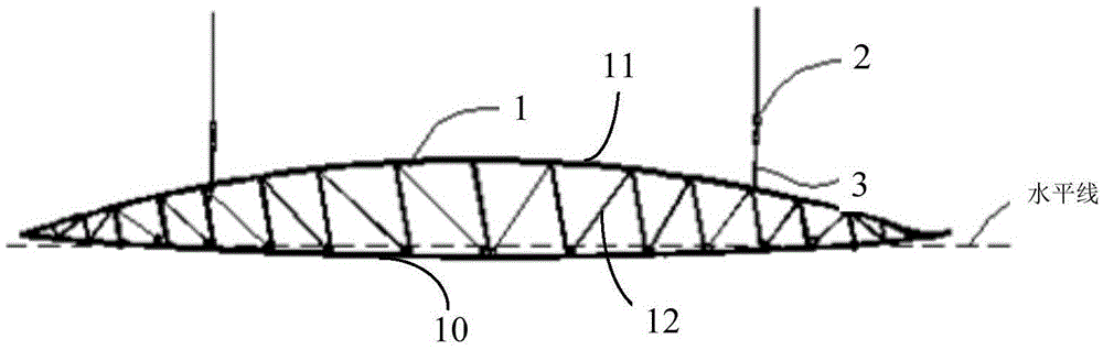
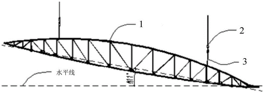
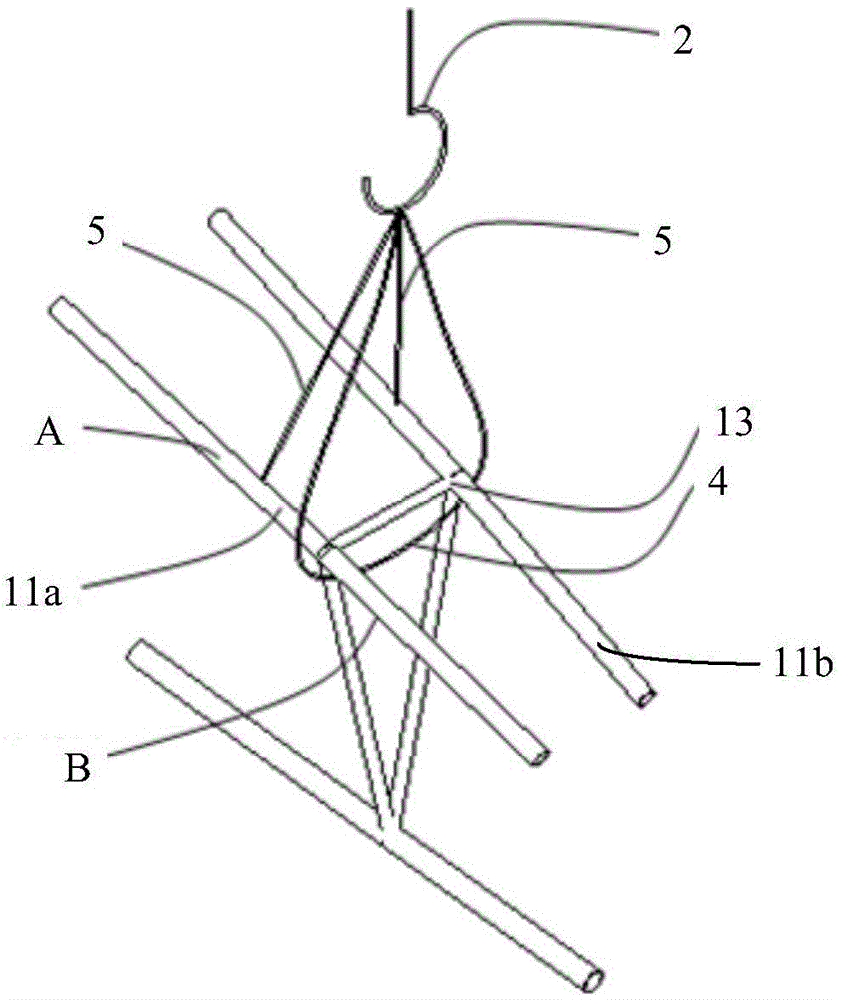
[0019] see Figure 1 to Figure 3 As shown, the method for hoisting the inclined shuttle-shaped space truss provided by the present invention is used for hoisting the large-span inclined shuttle-shaped space truss 1 . In this embodiment, the inclined shuttle-shaped space truss 1 is a space hyperbolic structure, its planar projection is a shuttle-shaped regular shuttle, and its front elevation projection is an inclined shuttle-shaped, with a maximum inclination angle of about 11°. The cross-section of the inclined shuttle-shaped space truss 1 is an irregular inverted triangle, and the elevations of ...


PUM


Abstract

The invention provides a method for hoisting an inclining shuttle-shaped space truss, which includes the following steps that: the truss is bound in a single-rope and double-pivot mode; two cranes are provided and two suspension points are arranged under the cranes; the truss is assembled and is horizontally hoisted after the assembly is finished; when a lifting height exceeds a low side in-situ height of the truss, the two cranes stop lifting; after the truss is stable, the low side crane stops lifting, and the high side crane continues lifting and finally stops lifting after the lifting height exceeds a high side in-situ height of the truss; the two cranes work cooperatively, so that big arms of the two cranes extend forward or withdraw backward, and the truss is hoisted to be right above the in-situ state; hooks are lowered from the cranes until two bearing balls of the truss fall on bearings at the tops of columns so as to finish the primary placement; the truss is corrected; and the bearing balls of the truss are welded on the bearings at the tops of the columns, and the track cranes loosen the hooks and the hoisting operation is finished. The above method lowers the hoisting height, reduces a horizontal stress generated by the hoisting operation, and enables horizontal hoisting members to be put in place rapidly and stably.

Description

technical field [0001] The invention belongs to the technical field of steel structures, and in particular relates to a method for hoisting an inclined shuttle-shaped space truss for hoisting the inclined shuttle-shaped space truss. Background technique [0002] With the development of the national economy, there is a strong demand for building more and larger buildings with large spaces and super-large spaces such as sports, leisure, exhibitions, airports, hangars, etc. This kind of building form is generally a space steel structure, and the structure type can be divided into grid frame (light steel), space truss (heavy steel) and so on. These buildings usually have the characteristics of large span, unique shape, complex stress and regional symbolic significance after completion. [0003] For such long-span building forms, traditional solid-web beams cannot meet the needs at all, and long-span spaces are often designed in the form of trusses during structural design. The...

Claims


Application Information

Patent Timeline
Patent Type & Authority Applications(China)
IPC IPC(8): E04G21/14
CPCE04G21/14
Inventor 徐坤孟祥冲甘宁邵校李松茂谭雨袁海军夏敖
Owner CHINA CONSTR SCI & IND CORP LTD
Why Eureka
Try Eureka