Method of measuring beam arrival time of particle accelerator

A particle accelerator and time-of-arrival technology, applied in measurement devices, radiation measurement, X/γ/cosmic radiation measurement, etc., can solve the problems of complex system structure, measurement error, inability to accurately obtain beam arrival time, etc. Phase-locking problem and the effect of solving measurement error problem

Active Publication Date: 2016-04-13
SHANGHAI INST OF APPLIED PHYSICS - CHINESE ACAD OF SCI +1
View PDF4 Cites 5 Cited by
  • Summary
  • Abstract
  • Description
  • Claims
  • Application Information

AI Technical Summary

Problems solved by technology

Among them, the electro-optic sampling method uses the beam signal coupled to the radio frequency probe with a broadband of tens of GHz to modulate the laser pulse intensity of the ultra-short reference clock, and obtains the beam arrival time information by detecting the modulated laser pulse intensity; this method The system structure used is relatively complex, and the reference laser pulse signal needs to be introduced into the accelerator tunnel, so debugging and optimization are relatively difficult
The RF phase cavity method uses a cavity beam probe (the operating frequency is usually in the order of GHz) to directly couple the narrowband signal carrying the beam arrival time information, and mixes the narrowband signal with the RF reference generated by the local oscillator signal source through a frequency mixing device. After the signal is mixed, an intermediate frequency signal is output, and the phase of the intermediate frequency signal reflects the relative time relationship between the beam signal and the reference signal; however, the RF phase cavity method needs to provide a stable RF reference signal, but this RF reference signal Usually susceptible to the influence of ambient temperature, which introduces measurement errors, so that the beam arrival time cannot be accurately obtained

Method used


Image

  • Method of measuring beam arrival time of particle accelerator
  • Method of measuring beam arrival time of particle accelerator
  • Method of measuring beam arrival time of particle accelerator

Examples


Embodiment Construction

[0017] Below in conjunction with the drawings, preferred embodiments of the present invention are given and described in detail.

[0018] At first basic principle of the present invention is introduced:

[0019] Cavity probes (such as cavity BPM) are used in the undulator part of free electron laser devices for beam position measurement due to their nm-level position resolution. The amplitude of the common mode TM010 signal output by the cavity probe is not affected by the position of the beam, but only related to the amplitude of the beam intensity, and the sex-to-noise ratio can reach more than 100dB, which can be used for beam intensity measurement.

[0020] The expression of the TM010 mode common mode signal V(t) output by the cavity probe is as follows:

[0021]

[0022] Among them, k is the scale factor of the probe induction signal, A is the amplitude of the beam current intensity, is the phase of the output signal when the beam passes through the cavity probe, τ ...


PUM


Abstract

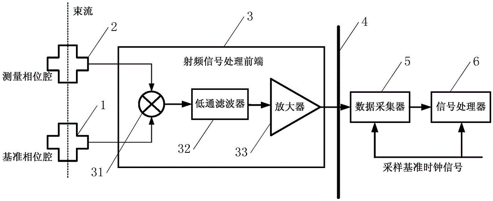
The invention relates to a method of measuring the beam arrival time of a particle accelerator. The method includes the following steps: S1, installing a first cavity type probe in an outlet of an electronic gun to serve as a reference phase cavity, and installing a second cavity type probe in an intersection of an electronic beam and seed laser to serve as a measurement phase cavity; S2, conducting frequency mixing on TM010 mode common mode signals output from the first cavity type probe and TM010 mode common mode signals output from the second cavity type probe, and conducting low-pass filtering and amplification on the signals that have undergone frequency mixing; S3, conducting synchronous digital sampling on the signals obtained in the step S2; and S4, performing digital signal processing on the signals sampled in the step S3 to obtain a beam phase, and obtaining the beam arrival time through calculation of the beam phase. The method solves the problem of attenuation caused by transmission radio frequency signals and the problem of measurement errors caused by indoor and outdoor temperature difference sensitivity, and also solves the problem in phase lock of a local oscillator source.

Description

technical field [0001] The invention relates to the field of accelerator physics beam diagnosis, in particular to a method for measuring the arrival time of particle accelerator beams. Background technique [0002] X-ray free electron laser device is a common particle accelerator, and the measurement of beam arrival time is one of its key technical issues. In order to improve the coincidence degree of the electron beam generated by the electron gun and the seed laser pulse generated by the laser generator in the three-dimensional real space in the external seed free electron laser device, it is necessary to accurately measure the arrival time of the electron beam and use this time as a reference To adjust the timing of the laser pulses, so as to realize the coincidence of the two in the direction of beam movement (time), the measurement resolution of the arrival time is required to reach the order of hundreds of fs or even higher. In addition, the change of the longitudinal...

Claims


Application Information

Patent Timeline
Patent Type & Authority Applications(China)
IPC IPC(8): G01T1/29
CPCG01T1/29
Inventor 冷用斌赖龙伟阎映炳
Owner SHANGHAI INST OF APPLIED PHYSICS - CHINESE ACAD OF SCI
Why Eureka
Try Eureka