Pressure detector and related display module thereof
A display module and detector technology, which is applied in the input/output process of instruments, data processing, electrical digital data processing, etc., can solve the problems of complex structure, lowering the yield rate of display modules, etc., and achieve the effect of simplifying complexity
- Summary
- Abstract
- Description
- Claims
- Application Information
AI Technical Summary
Problems solved by technology
Method used
Image

Examples
no. 1 example
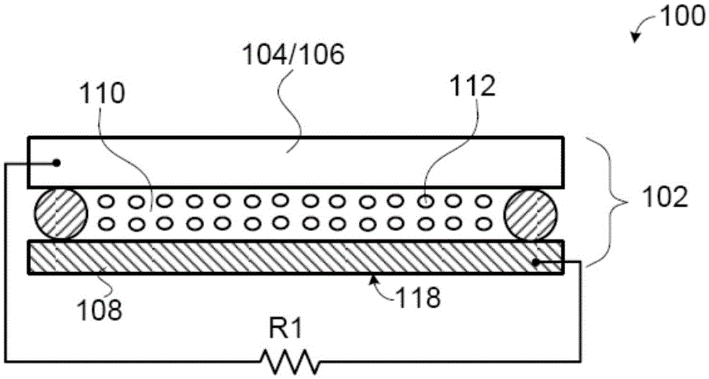
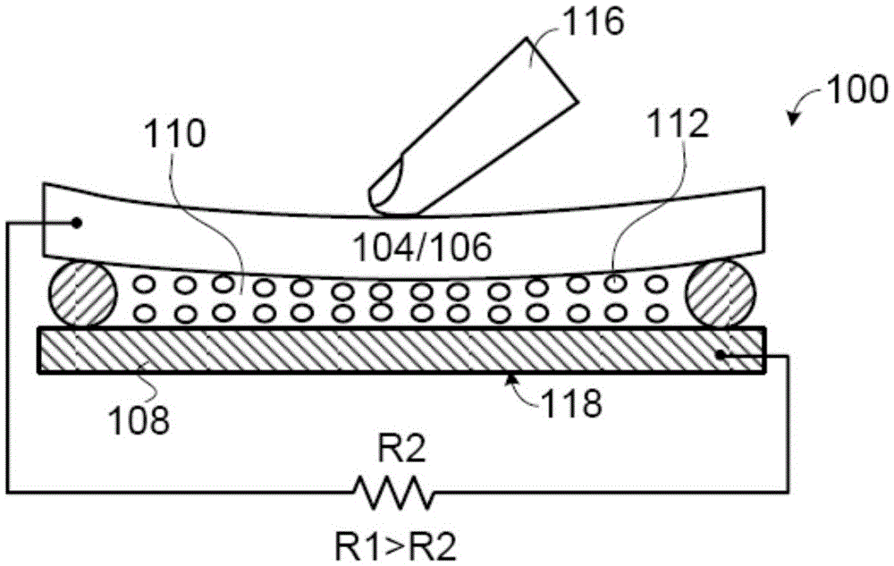
[0042] Please refer to FIG. 4A, which shows the first embodiment of the pressure detector. The pressure detector 430 includes: a first substrate 503 , an interposer 504 , and a second substrate 509 . Wherein, the first substrate 502 is a top substrate, and its material is metal. Therefore, the first substrate 502 is a metal substrate and can be used as an upper electrode layer. Furthermore, the second substrate 509 includes a bottom electrode layer 506 and a bottom substrate (bottom substrate) 508 , and the material of the bottom electrode layer 506 can be metal or indium tin oxide (ITO). Furthermore, the interposer 504 is located between the first substrate 502 and the lower electrode layer 506 , which can be a dielectric interposer or a resistive layer.
[0043] When the pressure detector 430 is a stand-alone pressure detector, the first substrate 502 (upper electrode layer) may further include a plurality of sub-upper electrodes (sub-electrode) and the lower electrode lay...
no. 2 example
[0047] Please refer to FIG. 4B, which shows a second embodiment of the pressure detector. The pressure detector 430 includes: a first substrate 512 , an interposer 514 , and a second substrate 519 . Wherein, the first substrate 512 is an upper substrate, and its material is metal. Therefore, the first substrate 512 is a metal substrate and can be used as an upper electrode layer. Furthermore, the second substrate 519 includes a lower electrode layer 518 and a lower substrate 516 , and the material of the lower electrode layer 518 can be metal or indium tin oxide (ITO). Furthermore, the interposer 514 is located between the first substrate 512 and the lower substrate 516 , which may be a dielectric interposer.
[0048] When the pressure detector 430 is a stand-alone pressure detector, the first substrate 512 (upper electrode layer) may further include a plurality of sub-upper electrodes and the lower electrode layer 518 may further include a plurality of sub-lower electrodes....
no. 3 example
[0052] Please refer to FIG. 4C, which shows a third embodiment of the pressure detector. The pressure detector 430 includes: a first substrate 525 , an interposer 526 , and a second substrate 528 . Wherein, the first substrate 525 includes an upper electrode layer 524 and an upper substrate 522, and the material of the upper electrode layer 524 can be metal or indium tin oxide film (ITO), and the upper substrate 522 can be a transparent substrate (such as a glass substrate or plastic substrate). The second substrate 528 is a lower substrate, and its material is metal. Therefore, the second substrate 528 is a metal substrate and can be used as the bottom electrode layer. Furthermore, the interposer 526 is located between the upper electrode layer 524 and the second substrate 528 , which can be a dielectric interposer or a resistive layer.
[0053] When the pressure detector 430 is an independent pressure detector, the upper electrode layer 524 may further include a plurality...
PUM
 Abstract
Description
Claims
Application Information
 - R&D
- Intellectual Property
- Life Sciences
- Materials
- Tech Scout
- Unparalleled Data Quality
- Higher Quality Content
- 60% Fewer Hallucinations
Browse by: Latest US Patents, China's latest patents, Technical Efficacy Thesaurus, Application Domain, Technology Topic, Popular Technical Reports.
© 2025 PatSnap. All rights reserved.Legal|Privacy policy|Modern Slavery Act Transparency Statement|Sitemap|About US| Contact US: help@patsnap.com