
Antenna control device, method and electronic equipment

A technology for antenna control and electronic equipment, applied in antenna coupling and other directions, can solve problems such as antenna efficiency loss, and achieve the effect of improving efficiency, reducing energy impact, and reducing efficiency loss

Active Publication Date: 2018-11-09
LENOVO (BEIJING) LTD
View PDF5 Cites 0 Cited by
  • Summary
  • Abstract
  • Description
  • Claims
  • Application Information

AI Technical Summary

Problems solved by technology

[0004] In view of this, the present invention provides an antenna control device, which solves the problem in the prior art that the efficiency of the antenna is lost during operation due to the absorption of signal energy between two antennas with relatively close spatial distances

Method used


Image

  • Antenna control device, method and electronic equipment
  • Antenna control device, method and electronic equipment
  • Antenna control device, method and electronic equipment

Examples


Embodiment Construction

[0060] The following will clearly and completely describe the technical solutions in the embodiments of the present invention with reference to the accompanying drawings in the embodiments of the present invention. Obviously, the described embodiments are only some, not all, embodiments of the present invention. Based on the embodiments of the present invention, all other embodiments obtained by persons of ordinary skill in the art without making creative efforts belong to the protection scope of the present invention.

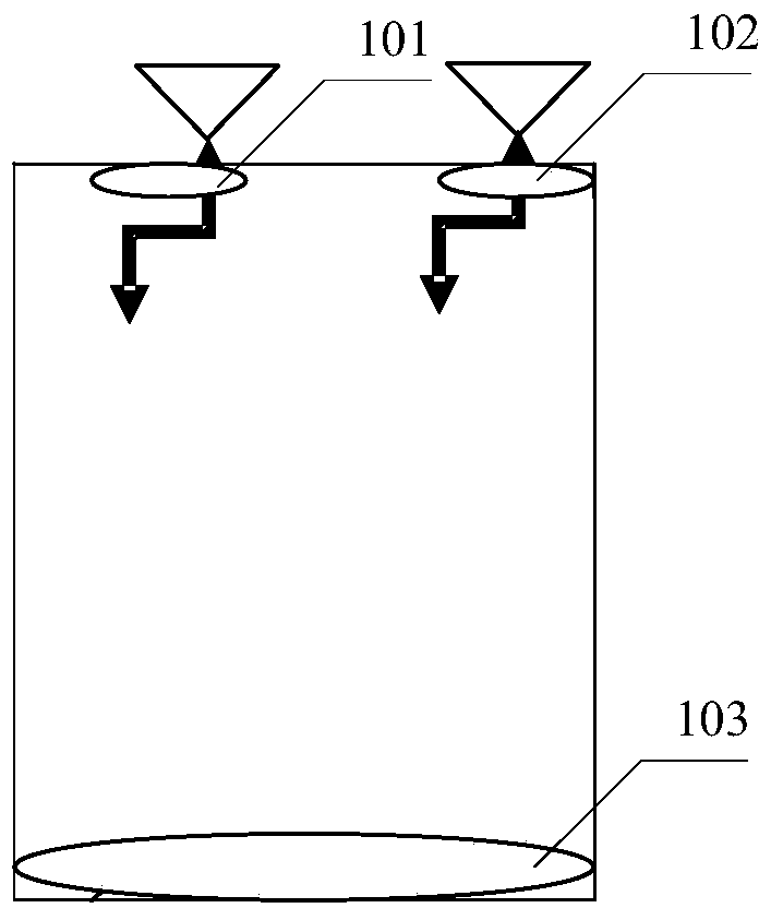
[0061] Please refer to the attached figure 1 , which is a distribution diagram of antennas in an electronic device in the prior art, including: a first antenna 101, a second antenna 102, and a third antenna 103, wherein the distance between the first antenna 101 and the second antenna 102 is relatively close, and it is easy to run There is a problem of absorbing signal energy, resulting in loss of efficiency of the antenna during operation, wherein the third a...


PUM


Abstract

The invention provides an antenna control apparatus. The apparatus is applied to electronic equipment provided with at least two antennas. The antenna control apparatus comprises a control circuit connected with a first antenna; when a first detector detects that a second antenna is operating, and when a second detector detects that the first antenna and the second antenna satisfy a preset condition, a controller adjusts parameters of the first antenna by changing the parameter changes of the control circuit to adjust a first influence value of the influence on the second antenna from the first antenna into a second influence value, wherein the second influence value is less than the first influence value. By adoption of the antenna control apparatus, when one of two adjacent antennas is in operation, the influence on the running antenna from the other antenna can be reduced by changing the parameters of the control circuit connected with the other antenna; namely, the influence on the energy for outward radiation from the signal emitted from the running antenna is reduced; the efficiency loss of the working antenna is reduced, and signal transmission efficiency of the electronic equipment with multiple antennas is improved.

Description

technical field [0001] The present invention relates to the field of mobile terminals, and more specifically, relates to an antenna control device, method and electronic equipment. Background technique [0002] With the advancement of electronic technology, more and more antennas are installed in electronic equipment, and each antenna corresponds to a specific frequency band to realize receiving and sending of signals in the frequency band. [0003] Since each antenna in an electronic device uses a conductor and sends signals to the external space through the conductor antenna, when the space distance between any two antennas is relatively close, due to the inductive characteristics of the conductor, the connection between two antennas using the same material It is easy to generate induction between the working antennas, that is, when one antenna is working, the other antenna will absorb the signal energy sent by the working antenna, resulting in the reduction of the energy ...

Claims


Application Information

Patent Timeline
Patent Type & Authority Patents(China)
IPC IPC(8): H01Q1/52
Inventor 洪晓锋
Owner LENOVO (BEIJING) LTD
Learn More