
valve

A technology of valve core and valve sleeve, which is applied in the field of valves, can solve the problem of increasing the burden of switching speed and achieve the effect of small sliding friction

Inactive Publication Date: 2017-12-01
FESTO AG & CO KG
View PDF10 Cites 0 Cited by
  • Summary
  • Abstract
  • Description
  • Claims
  • Application Information

AI Technical Summary

Problems solved by technology

The disadvantage here is that the spool can only be moved by applying a relatively high drive force, which increases the switching speed
In addition, there is the problem that the lubricant that may be applied to the outer peripheral surface of the valve core is scraped off by the tightly abutting sealing element, so that the valve core can be observed to adhere especially after long operating intervals. Tendency at the sealing element, which can only be compensated by a higher drive force with a correspondingly higher energy consumption

Method used


Image

  • valve
  • valve
  • valve

Examples


Embodiment Construction

[0031] Unless otherwise stated, the following explanations apply to all embodiments.

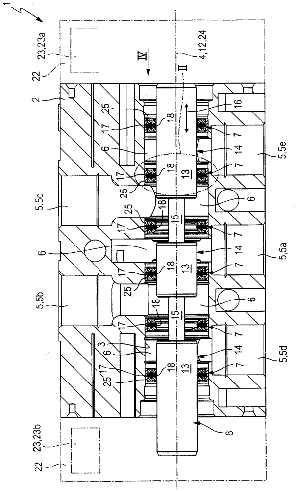
[0032] The valve indicated overall by the reference numeral 1 preferably has the design as a multi-way valve and has a valve housing 2 in which a recess 3 having a linear elongated, preferably cylindrical contour, is formed. The recess 3 has an imaginary central longitudinal axis 4 which is outlined with a dash-dotted line.

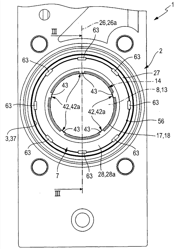
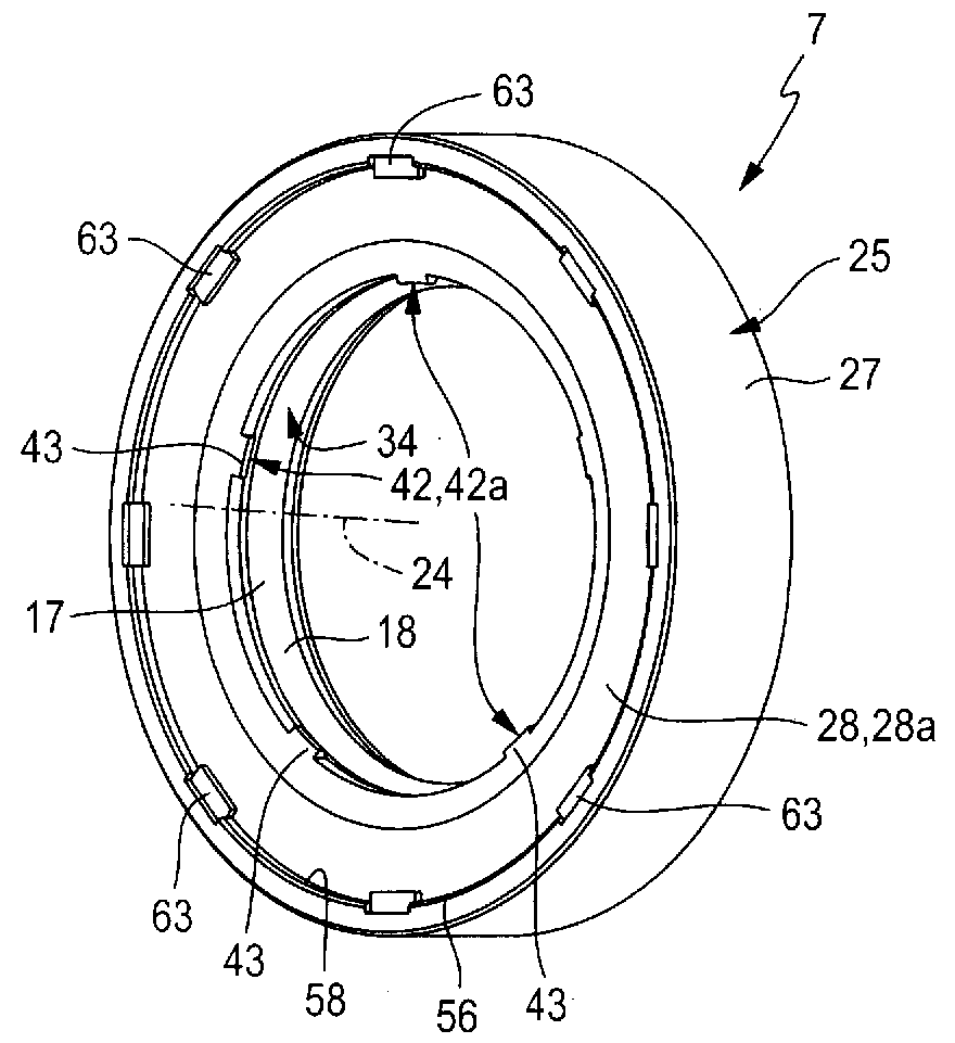
[0033] A plurality of valve channels 5 , which pass through the valve housing 2 , open into the recess 3 at locations axially spaced from one another in the periphery. Between the gap section 6 of the gap 3 that communicates with a corresponding one of the valve passages 5, a corresponding sealing ring 7 with a special structure is placed in the gap 3, and further The structure of the sealing ring is discussed. In any case, preferably a plurality of sealing rings 7 having a coaxial arrangement and an axial spacing from one another are arranged in the recess 3 .

[00...


PUM


Abstract

A valve includes at least one seal ring arranged in a recess of a valve housing, which seal ring has a seal housing having a U-shaped cross-section, in which an annular sealing element is arranged. At least one of the two housing legs of the seal housing is designed as a guiding leg, which effects transverse support and linear displacement guidance of a valve slide that passes through the seal ring.

Description

technical field [0001] The invention relates to a valve with a valve sleeve (Ventilgehäuse) and a piston-shaped valve slide (Ventilschieber), which can be moved between different operating positions while performing a linear switching movement (Umschaltbewegung). It is arranged axially displaceable in a recess of the valve sleeve with a central longitudinal axis, and the valve also has at least one sealing ring coaxially enclosing the valve insert in the recess, the sealing ring having An annular sealing housing with a U-shaped cross-section and two opposite housing arms (Gehäuseschenkel), fixed in position relative to the valve housing, which encloses a Receptacle chamber, which radially inside has a slit-shaped housing opening laterally bounded by two housing arms and in which an annular sealing element is arranged coaxially , the sealing element is configured, on the one hand, to cooperate statically and sealingly with the inner surface of the sealing housing and, on the o...

Claims


Application Information

Patent Timeline
Patent Type & Authority Patents(China)
IPC IPC(8): F16K11/07F15B13/04
CPCF16K11/0712
Inventor M.贝尔纳F.雷普克
Owner FESTO AG & CO KG
Learn More