Anti-blocking power mechanism of spherical compressor

A technology of spherical compressors and power mechanisms, which is applied in the direction of machines/engines, mechanical equipment, and swing piston pumps, can solve the problem that spherical compressors cannot adapt to microstructures, the advantages of spherical compressor surface seals are reduced, concave slideways and Guide pin wear and other problems, to achieve good coolant lubrication effect, stable and reliable operation of the mechanism, and prevent the mechanism from being stuck

Active Publication Date: 2015-01-28
XIAN ZHENGAN ENVIRONMENTAL TECH
View PDF5 Cites 13 Cited by
  • Summary
  • Abstract
  • Description
  • Claims
  • Application Information

AI Technical Summary

Problems solved by technology

However, when the main shaft rotates until the axis of the turntable coincides with the axis of the piston, the dead point of the mechanism movement will occur, which will easily cause the mechanism to be stuck and unable to rotate, especially for the working conditions of small structure size, poor lubrication and high pressure ratio, the phenomenon of stagnation is more obvious
[0003] Chinese patent Nos. 201310100697.5 and 201410100390.X, the patent titles are "A Turntable Rotation Synchronization Mechanism for Spherical Compressors" and "A Spherical Compressor Rotor Anti-Seize Mechanism", respectively, the spherical compressor rotor is at the dead point The problem of stagnation is fundamentally solved, but during the implementation of the patent "A Turntable Rotation Synchronization Mechanism for Spherical Compressors", since the turntable synchronization mechanism is set between the spherical surface of the turntable and the spherical surface of the cylinder, The concave slideway reduces the sealing area on the matching spherical surface, and even becomes a gas leakage channel between the working chambers, which reduces the sealing advantage of the spherical compressor surface, so that the spherical compressor cannot adapt to the microstructure to work under high pressure conditions , the efficiency is reduced; during the implementation of "A Spherical Compressor Rotor Anti-Seize Mechanism", the guide pin slides in the concave slideway, and the guide pin must cooperate well with the concave slideway, and the guide pin is supported by the concave slideway Constraints, the concave slides are distributed on the sliding track of the corresponding cylinder seat spherical surface or the cylinder lower spherical surface during the rotation of the turntable. The concave slides are complex to process, and the concave slides and guide pins are severely worn. Cause early failure, and the guide pin will be stuck in the concave slideway due to machining errors or positional deviation during movement, forming a new stuck point
At the same time, due to the high-pressure volume formed by the relative movement of the piston and the turntable, the turntable spherical surface produces partial pressure on the cylinder spherical surface. The higher the output pressure of the compressor, the greater the unbalanced pressure generated by the turntable on the cylinder body. Balancing the partial pressure increases the friction between the turntable and the cylinder body, resulting in abnormal wear of the turntable and cylinder body, and it is also easy to cause the rotor movement to get stuck

Method used


Image

  • Anti-blocking power mechanism of spherical compressor
  • Anti-blocking power mechanism of spherical compressor
  • Anti-blocking power mechanism of spherical compressor

Examples


Embodiment Construction

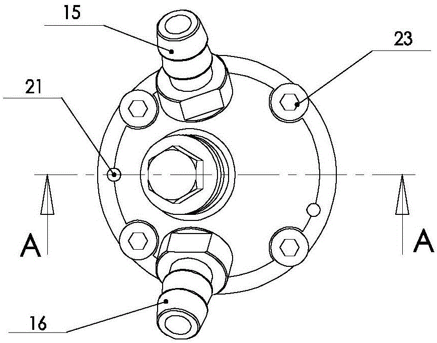
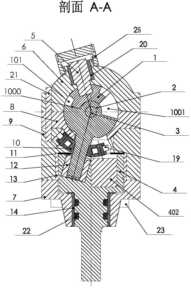
[0042] Such as figure 1 , figure 2 As shown, the spherical compressor includes a piston 1, a turntable 2, a center pin 3, a main shaft 4, a cylinder head 6, a cylinder body 8, a cylinder body seat 9 and a main shaft support 7, a cylinder head 6, a cylinder body 8, a cylinder body seat 9, The main shaft support 7 is connected successively by connecting screws 23 to form a casing of a spherical compressor; Figure 5 , Figure 6 and Figure 7 As shown, the cylinder head 6 and the cylinder body 8 have a hemispherical inner surface, and are connected by connecting screws 23 to form a spherical inner cavity of a spherical compressor. The cylinder block seat 9 is connected to the lower part of the cylinder body 8 by connecting screws 23. In order to ensure that the spherical surfaces fit together The positioning is accurate, and positioning pins 21 are arranged at the connecting parts of the cylinder head 6, the cylinder body 8 and the cylinder body seat 9.

[0043] in such as ...


PUM


Abstract

The invention discloses an anti-blocking power mechanism of a spherical compressor. A rotating plate synchronous power mechanism consisting of a power handle (10) and a track limiting surface (24) is arranged between a cylinder body (8) and a cylinder body seat (9), the power handle (10) is of a dumbbell structure with two symmetric ends, is fixed on a rotating plate shaft (203) and rotates along with a rotating plate (2), when the rotating plate (2) rotates to a position at which the axis of the rotating plate is overlapped with the axis of a piston, the rotating plate (2) is driven by the rotation of a main shaft (4), the rotating plate synchronous power mechanism can produce power enabling the rotating plate (2) to rotate continuously around the axis, so that a rotor continuously rotates and crosses a dead point; the rotating plate is provided with a backpressure support, so that the local imbalance pressure produced by a rotating plate spherical surface on the spherical surface of the cylinder body due to the working high pressure can be reduced, the mechanism can operate firmly and reliably, and the blocking problem of the rotor of the spherical compressor can be thoroughly solved.

Description

technical field [0001] The patent of the present invention relates to an anti-seize dynamic mechanism of a spherical compressor. Background technique [0002] Spherical compressor technology is a new discipline developed in recent years. It is completely different from the structure and principle of existing compressors. The rotation of the main shaft drives the relative movement of the piston and the turntable arranged in the spherical inner cavity, forming a compressor in space. One or more pairs of working chambers whose volumes are constantly changing to produce compression and expansion have the advantages of no inlet / exhaust valve, less moving parts, less vibration, high mechanical efficiency, reliable sealing, etc., especially in the field of micro compressors , High compression ratio pump machinery has more obvious advantages. At present, the spherical compressor technology has obtained many patents at home and abroad. However, when the main shaft rotates until the...

Claims


Application Information

Patent Timeline
Patent Type & Authority Applications(China)
IPC IPC(8): F04C18/00F04C29/00
CPCF04C21/002F04C29/005
Inventor 王陆一
Owner XIAN ZHENGAN ENVIRONMENTAL TECH
Why Eureka
Try Eureka