Gear dead-point-passing mechanism of spherical compressor

A spherical compressor and over-dead point technology, which is applied in the direction of machines/engines, mechanical equipment, liquid fuel engines, etc., can solve the problems of rotation sticking, mechanism sticking, rotation, etc., and achieve the effect of reliable operation of the anti-blocking mechanism

Active Publication Date: 2016-07-13
深圳市球形动力科技有限公司
View PDF6 Cites 0 Cited by
  • Summary
  • Abstract
  • Description
  • Claims
  • Application Information

AI Technical Summary

Problems solved by technology

[0003] Since the rotation of the piston is powered by the eccentric main shaft, when the main shaft rotates until the axis of the turntable coincides with the axis of the piston, the resultant force of the main shaft acting on the turntable is perpendicular to the axis of the piston and the turntable, so that the torque of the turntable rotating around the axis of the piston is zero. The piston cannot be rotated, causing the mechanism to jam, which is the dead center of motion of the mechanism
The force analysis is as follows: the main shaft rotates under the drive of the motor, and the main shaft acts on a driving force of the turntable. This driving force has a component force to make the piston rotate around its axis, driving the turntable pin in the eccentric oblique hole of the main shaft to rotate. Near the position where the axis of the turntable and the axis of the piston are close to coincident, the torque generated by the component force that makes the piston rotate becomes smaller and smaller until it becomes zero, so the piston cannot obtain enough torque around it before and after the axis of the piston and the axis of the turntable are close to coincident. The axis rotates, so that the phenomenon of rotation stagnation occurs near this position, resulting in the motion dead point of the mechanism; when the motion dead point is the initial state or stops rotating in this state, it will not be able to start next time

Method used


Image

  • Gear dead-point-passing mechanism of spherical compressor
  • Gear dead-point-passing mechanism of spherical compressor
  • Gear dead-point-passing mechanism of spherical compressor

Examples


Embodiment Construction

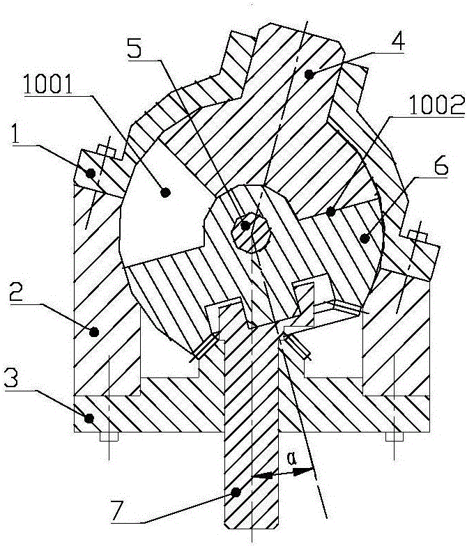
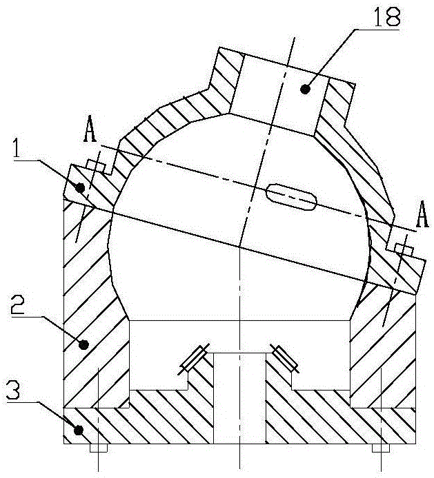
[0021] Such as figure 1 , figure 2 As shown, the spherical compressor includes a cylinder head 1, a cylinder body 2, a main shaft support 3, a piston 4, a central pin 5, a turntable 6, etc., and the cylinder head 1, cylinder body 2, and main shaft support 3 are sequentially connected by connecting screws to form a spherical compressor The casing; the cylinder head 1 and the cylinder body 2 have a hemispherical inner surface, and are connected by connecting screws to form a spherical inner cavity of a spherical compressor.

[0022] in such as Figure 8 , Figure 9 As shown, the piston 4 has a spherical top surface, a piston shaft 15 in the center of the spherical top surface, two sides at a certain angle, and a piston pin seat formed at the bottom of the two sides of the piston 4. The piston pin seat is a semi-cylindrical structure, and the semi-cylindrical There is a groove in the middle part, and a through piston pin hole 16 is arranged on the axial direction of the pisto...


PUM


Abstract

The invention discloses a gear dead-point-passing mechanism of a spherical compressor.A conical surface inner gear ring (12) is arranged at the lower end of a concave cavity of a rotating plate (6).A conical surface outer gear ring (14) meshed with the conical surface inner gear ring (12) is arranged at the upper end of a main shaft support (3).In the rotating process of a main shaft (7), the conical surface outer gear ring (14) and the conical surface inner gear ring (12) are always meshed, the pitch diameter of the conical surface inner gear ring (12) is twice that of the conical surface outer gear ring (14), and the number of teeth of the conical surface inner gear ring (12) is twice that of teeth of the conical surface outer gear ring (14).In the movement dead point of the mechanism, the torque which is supported by the tooth meshing point of the conical surface inner gear ring (12) and the conical surface outer gear ring (14) and makes a piston (4) rotate around the axis of itself is formed on the rotating plate (6).The piston (4) and the rotating plate (6) continue to rotate around the axes of themselves, so dead-point-free running is achieved.

Description

technical field [0001] The patent of the present invention relates to a gear over dead center mechanism of a spherical compressor. Background technique [0002] The structure and principle of the spherical compressor are completely different from the existing compressors. The rotation of the main shaft drives the piston and the turntable in the spherical inner cavity to generate relative motion, forming a pair or more pairs of working chambers with continuously changing volumes in the space. Compression and expansion are generated, and its advantages are no inlet / exhaust valve, less moving parts, small vibration, high mechanical efficiency, reliable sealing, etc. The spherical compressor is a major invention in the structure of the compressor in recent years. At present, the spherical compressor A lot of progress has been made in the application research of compressor technology, and many patents have been obtained at home and abroad. Various power machinery based on spheric...

Claims


Application Information

Patent Timeline
Patent Type & Authority Applications(China)
IPC IPC(8): F04C21/00F04C29/00
CPCF04C21/00F04C29/00
Inventor 王陆一
Owner 深圳市球形动力科技有限公司
Why Eureka
Try Eureka