Fly-by-wire system for an aircraft

A fly-by-wire control system and technology of the control system, applied in the field of fly-by-wire control systems, can solve problems such as the mass and volume of the fly-by-wire control system, and achieve the effect of reducing volume and quality

Active Publication Date: 2016-04-13
SAGEM DEFENSE SECURITE SA +1
View PDF6 Cites 2 Cited by
  • Summary
  • Abstract
  • Description
  • Claims
  • Application Information

AI Technical Summary

Problems solved by technology

[0010] The fly-by-wire sy

Method used


Image

  • Fly-by-wire system for an aircraft
  • Fly-by-wire system for an aircraft
  • Fly-by-wire system for an aircraft

Examples


Embodiment Construction

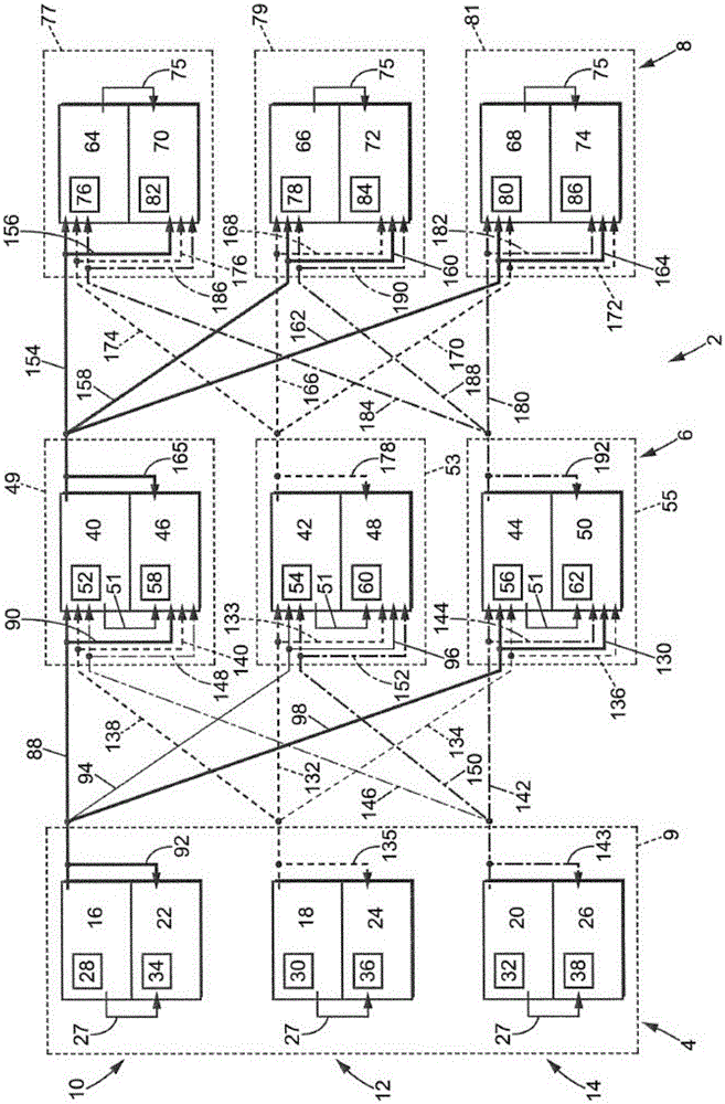
[0122] refer to figure 2 , the control system 2 according to the invention comprises a pilot control device 4 , a position calculation device 6 of a flight control surface and an actuator control device 8 .

[0123] The pilot control device 4 comprises three stages 10 , 12 , 14 arranged in a miniature joystick 9 , the joystick or control lever hereinafter referred to as joystick 9 . Each stage 10, 12, 14 includes a main computer, hereinafter referred to as the control computer 16, 18, 20, and a redundant computer, hereinafter referred to as the supervisory computer 22, 24, 26. The computers are connected by communication links 27 to their corresponding stage control computers.

[0124] The control computer 16 and the supervisory computer 22 of the first stage 10 are formed by two printed circuit boards arranged opposite each other. Usually, by figure 2 with Figure 4 The set of control computer and supervisory computer represented by the two side-by-side rectangles in is...


PUM


Abstract

The invention relates to a fly-by-wire system which comprises: three-stage piloting control (4), each stage including a control computer (16, 18, 20) suitable for determining the positions of the stick, and a monitoring computer (22, 24, 26) capable of verifying all the pre-determined positions of the stick; three-stage control-surface position calculation (6), each stage including a control computer (40, 42, 44) suitable for calculating the control-surface positions from encoded positions of the stick, and a monitoring computer (46, 48, 50) capable of verifying all the calculated control-surface positions; a single unidirectional communication link (88) connecting the control computer (16) of the first piloting control stage to the control computer (40) of the first control-surface position calculation stage; a single unidirectional communication link (132) connecting the control computer (18) of the second piloting control stage to the control computer (42) of the second control-surface position calculation stage; and a single unidirectional communication link (142) connecting the control computer (20) of the third piloting control stage to the control computer (44) of the third control-surface position calculation stage.

Description

technical field [0001] The invention relates to an aircraft fly-by-wire control system. Background technique [0002] Fly-by-wire systems are gradually being applied to more and more aircraft. The first fly-by-wire system was replicated with a mechanically controlled manual backup system, enabling manual landing in the event of a fly-by-wire system failure. However, such manual controls are bulky and heavy, so manufacturers today no longer design aircraft that include such manual backup controls. [0003] In this light, it is important that fly-by-wire systems have a high level of safety. To guarantee this level of security, redundant processors are implemented and communication links are duplicated. [0004] E.g, figure 1 A known fly-by-wire system is shown in . It comprises a pilot control device 100, a position calculation device 102 of a flight control surface, and an actuator control device 104, said pilot control device being suitable for determining the position ...

Claims


Application Information

Patent Timeline
IPC IPC(8): G05D1/00
CPCG05D1/0077B64C13/505B64C13/503
Inventor 塞德里克·巴拉克里斯托菲·蒂齐埃里克·鲍尔戈格内帕斯卡尔·科佩亚恩·文登巴维埃雷
Owner SAGEM DEFENSE SECURITE SA
Why Eureka
Try Eureka