Dynamic cleaning water outlet device

A water outlet device and cleaning technology, which is applied in the direction of spraying devices, spraying devices, etc., can solve problems such as manual intervention, and achieve the effect of reducing water pressure loss and good cleaning effect

Active Publication Date: 2016-04-20
XIAMEN SHUIDA SANITARY WARE
View PDF6 Cites 18 Cited by
  • Summary
  • Abstract
  • Description
  • Claims
  • Application Information

AI Technical Summary

Problems solved by technology

[0007] Aiming at the deficiencies of the prior art, the object of the present invention is to provide a dynamic cleaning water outlet device. When the water outlet device is used for showering, when the water channel is opened, the cleaning needle can continuously move up and down to realize dynamic

Method used


Image

  • Dynamic cleaning water outlet device
  • Dynamic cleaning water outlet device
  • Dynamic cleaning water outlet device

Examples


Embodiment 1

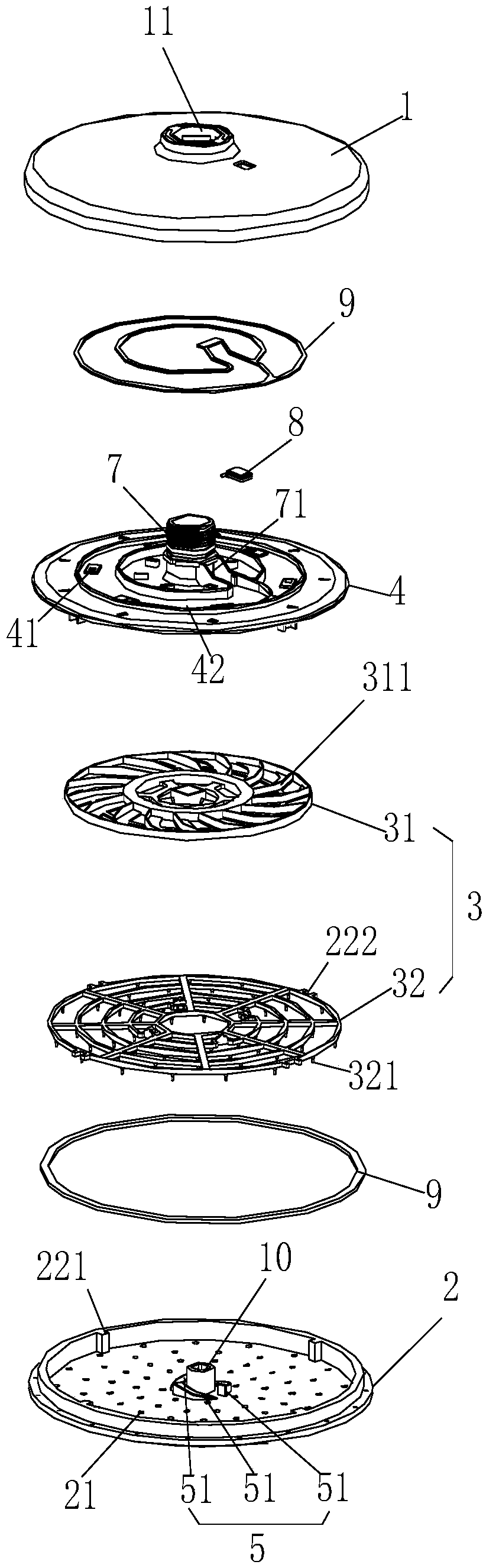
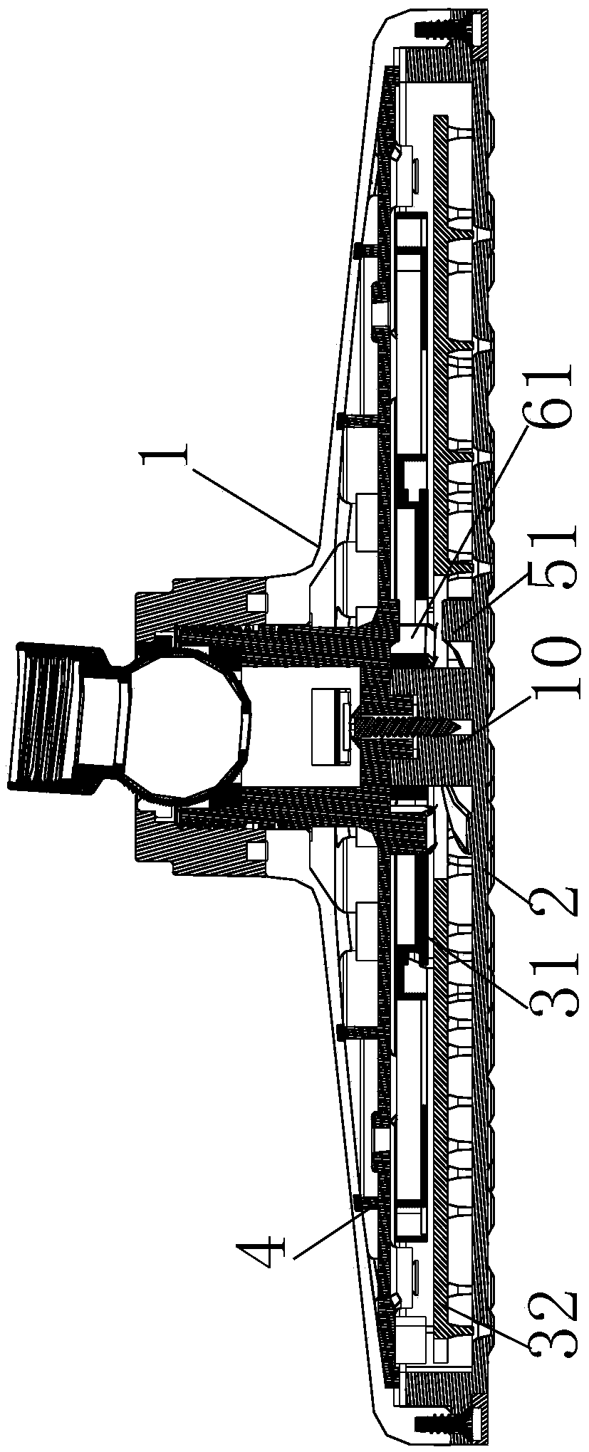
[0040] Reference Figure 1-Figure 3 The dynamic cleaning water outlet device described in this embodiment is specifically a top spray; it includes a body 1, a water outlet panel 2 provided on the body 1, and a storage cavity is formed between the body 1 and the water outlet panel 2 ; The body 1 is provided with a water inlet 11, and the water outlet panel 2 is provided with a water outlet 21;

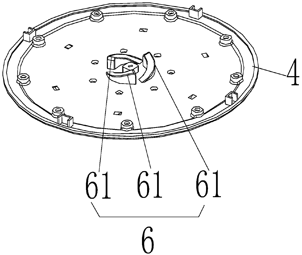
[0041] An inclined water body 4 and a cleaning dial 3 are sequentially installed in the receiving cavity from top to bottom; the water outlet panel 2 is provided with a rotating shaft 10; the cleaning dial 3 includes a rotatably sleeved on the rotating shaft 10 The rotating disk 31, a dial 32 that is clamped under the rotating disk 31 and can rotate relative to the rotating disk 31, the dial 32 is provided with a cleaning needle 321 corresponding to the water outlet 21, and the rotating disk 31 is provided with The fan blade structure 311 that drives the rotating disc 31 to rotate under th...

Embodiment 2

[0052] Reference Figure 4-Figure 6 , The dynamic cleaning water outlet device described in this embodiment is specifically a hand-held shower; it includes a body 1, a water outlet panel 2 provided on the body 1; a storage is formed between the body 1 and the water outlet panel 2 Cavity; the body 1 is provided with a water inlet 11, and the water outlet panel 2 is provided with a water outlet 21;

[0053] An oblique water body 4 and a cleaning dial 3 are sequentially installed in the receiving cavity from top to bottom; the oblique water body 4 is provided with a rotating shaft 10; the cleaning dial 3 includes a rotation rotatably sleeved on the rotating shaft 10 Disk 31, a dial 32 that is clamped under the rotating disk 31 and can rotate relative to the rotating disk 31, the dial 32 is provided with a cleaning needle 321 corresponding to the water outlet 21, and the rotating disk 31 is provided with The fan blade structure 311 that drives the rotating disc 31 to rotate under th...


PUM


Abstract

The invention discloses a dynamic cleaning water outlet device which comprises a body and a water outlet panel arranged on the body. A containing cavity is formed between the body and the water outlet panel, a water inclining body and a cleaning needle plate are installed in the containing cavity in sequence from top to bottom; a rotating shaft is arranged on the water inclining body and/or the water outlet panel; the cleaning needle plate comprises a rotary disc and a needle plate body, and the rotary disc has a fan blade structure; guiding holes are formed in the water inclining body; a limiting device is further arranged in the containing cavity; a first guiding mechanism which is used for making the horizontal height of the water outlet panel increased when the rotary disc rotates is arranged on the water outlet panel, a second guiding mechanism which is used for making the horizontal height of the water inclining body decreased when the rotary rotates is arranged on the end face, corresponding to the first guiding mechanism, of the water inclining body, and the cleaning needle plate can move up and down along the rotating shaft under the acting force of water pressure. When the dynamic cleaning water outlet device is adopted for a shower and the water way is opened, cleaning needles can move up and down continuously, dynamic cleaning during the shower is achieved, and the dynamic cleaning water outlet device has the advantage of being good in cleaning effect.

Description

Technical field [0001] The invention relates to the technical field of shower heads, in particular to a dynamic cleaning water outlet device. Background technique [0002] The invention patent with the Chinese patent application number "201410516738.3" discloses a top spray cleaning device, which includes a main body, a water outlet panel, a cleaning needle, a lever and a lever drive mechanism; the water outlet panel is buckled with the main body to form an accommodation cavity, and the cleaning needle, lever and The lever drive mechanism is placed in the accommodating cavity; the water outlet panel has a water outlet hole, and the cleaning needle is movably arranged relative to the water outlet panel and corresponds to the water outlet hole; the lever connects the force end to the lever drive mechanism, and the force end to the cleaning needle, lever The driving mechanism is provided with a reset spring; the lever driving mechanism drives the lever to swing, and the force end of...

Claims


Application Information

Patent Timeline
IPC IPC(8): B05B1/18B05B1/30B05B15/02
CPCB05B1/18B05B1/30B05B15/5223
Inventor 郭建华李真
Owner XIAMEN SHUIDA SANITARY WARE
Why Eureka
Try Eureka