
Shaft part drilling fixture

A technology for drilling fixtures and shaft parts, which is applied to metal processing mechanical parts, clamping, clamping devices, etc., can solve the problems of not being able to clamp multiple shaft parts at the same time, poor positioning effect, and low work efficiency. Achieve the effect of reducing processing cost, improving work efficiency and ensuring processing quality

Inactive Publication Date: 2016-04-20
SICHUAN SPACEFLIGHT SHIDONG AUTO PARTS CO LTD
View PDF5 Cites 14 Cited by
  • Summary
  • Abstract
  • Description
  • Claims
  • Application Information

AI Technical Summary

Problems solved by technology

[0003] The technical problem to be solved by the present invention is to provide a drilling jig for shaft parts to overcome the poor positioning effect of the drilling jig for shaft parts in the prior art, the inability to clamp multiple shaft parts at the same time, and low work efficiency. defect

Method used


Image

  • Shaft part drilling fixture
  • Shaft part drilling fixture
  • Shaft part drilling fixture

Examples


Embodiment Construction

[0017] The present invention will be described in further detail below in conjunction with the accompanying drawings.

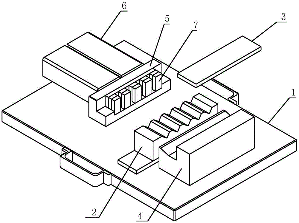
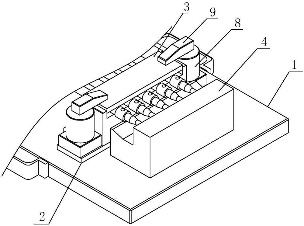
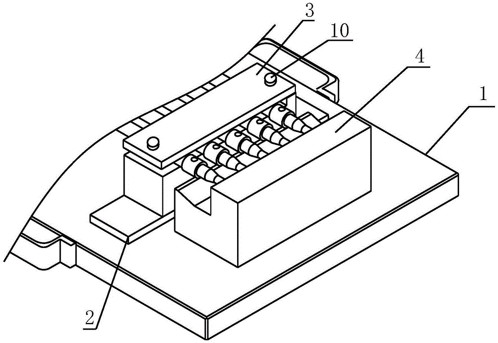
[0018] Such as figure 1 As shown, a drilling jig for shaft parts provided by the present invention includes a base plate 1 and a support plate 2 located on the base plate 1. The support plate 2 is fixedly connected to the base plate 1 and can be an integral structure or can be tightened by bolts. The upper end of the support plate 2 is provided with a plurality of V-shaped grooves for placing a plurality of shaft parts so that the shaft parts will not slide on the support plate 2 .

[0019] The present invention also includes a pressing plate 3, a top plate 4, a moving plate 5 and a cylinder 6, the support plate 2 is located between the moving plate 5 and the top plate 6, the top plate 4 is fixedly connected with the bottom plate 1, and the height of the top plate 4 is greater than that of the support The height of the plate 2, so that when the shaft parts a...


PUM


Abstract

The invention relates to the technical field of machining, in particular to a shaft part drilling fixture. The fixture comprises a baseplate and a support plate positioned on the baseplate, and further comprises a pressing plate, a top plate, a moving plate and a cylinder; the top plate is fixedly connected with the baseplate; the support plate is positioned between the moving plate and the top plate; the pressing plate is detachably connected with the support plate through a locking device; the moving plate is positioned on the baseplate, and is fixedly connected with the cylinder; and multiple nonmetal elastic gaskets are arranged on the moving plate. The moving plate performs a linear reciprocating motion on the baseplate through the cylinder to tightly press a shaft part, so that the shaft part cannot rotate during remachining, and the machining precision is guaranteed. The pressing plate is arranged on the support plate, and is locked through the locking device for further fixing the shaft part, so that the machining quality is guaranteed. The fixture can synchronously clamp multiple shaft parts to satisfy synchronous machining requirement, so that the working efficiency is improved, and the enterprise machining cost is reduced.

Description

technical field [0001] The invention relates to the technical field of machining, in particular to a drilling jig for shaft parts. Background technique [0002] When machining holes on shaft parts, because the shaft parts are easy to rotate, it is difficult to locate the position of the hole, resulting in large size deviation and inconsistent axis lines of the two holes. In order to avoid this situation, the usual method is to use tools such as pliers to clamp the shaft parts and then process them. However, the fastening effect of this method is not good, and the precision of the processed parts is low. Moreover, most of the existing clamps can only clamp one part at a time, and cannot clamp multiple shaft parts at the same time, which often leads to low work efficiency and increases the processing cost of the enterprise. Contents of the invention [0003] The technical problem to be solved by the present invention is to provide a drilling jig for shaft parts to overcome ...

Claims


Application Information

Patent Timeline
Patent Type & Authority Applications(China)
IPC IPC(8): B23Q3/08
CPCB23Q3/069B23Q3/061B23Q2703/04
Inventor 刘光亚代占省刘林祥
Owner SICHUAN SPACEFLIGHT SHIDONG AUTO PARTS CO LTD
Learn More